Injection Stretch Blow Molding Machine
A comprehensive, first-principles guide to maximizing uptime, eliminating defects,
and extending the service life of your ISBM equipment.
🔧 Fault Diagnosis
🏭 OEM Best Practices
An injection stretch blow molding machine is one of the most sophisticated and capital-intensive pieces of equipment in modern plastics manufacturing. Producing precision hollow containers — from pharmaceutical bottles to cosmetic packaging and food-grade PET beverages — these machines integrate injection molding, thermal conditioning, mechanical stretching, and high-pressure blow molding into a continuous, synchronized cycle. Their mechanical complexity makes them highly productive, but it also means that without disciplined maintenance and systematic troubleshooting, costly breakdowns and product quality failures are almost inevitable.
This guide is written for plant engineers, maintenance technicians, and production managers who need a thorough, practical reference for keeping ISBM equipment running at peak performance. Whether you manage a single unit or an entire production floor, the principles here apply universally — covering daily inspections, scheduled preventive maintenance, component-level servicing, and systematic fault diagnosis using first-principles engineering reasoning.
Understanding not just what to do but why each maintenance task matters is the foundation of genuine machine expertise. This guide gives you that depth of understanding so you can adapt procedures to your specific model, operating environment, and production demands with confidence.
Understanding the Injection Stretch Blow Molding Process
Before maintaining a machine with confidence, you must understand exactly how it works.
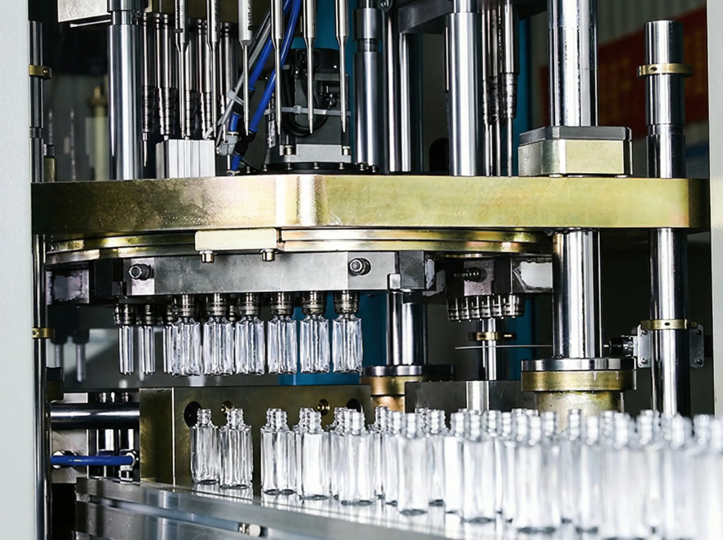
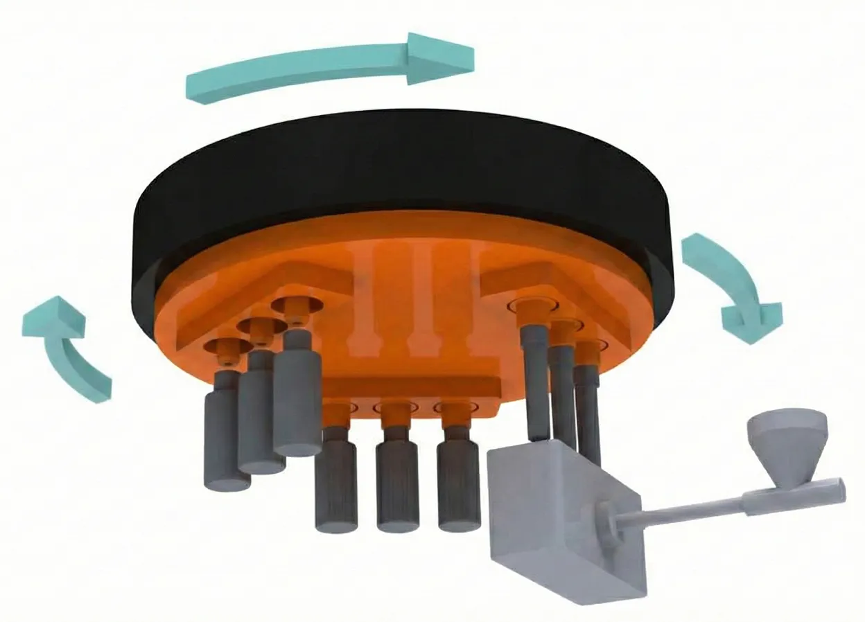
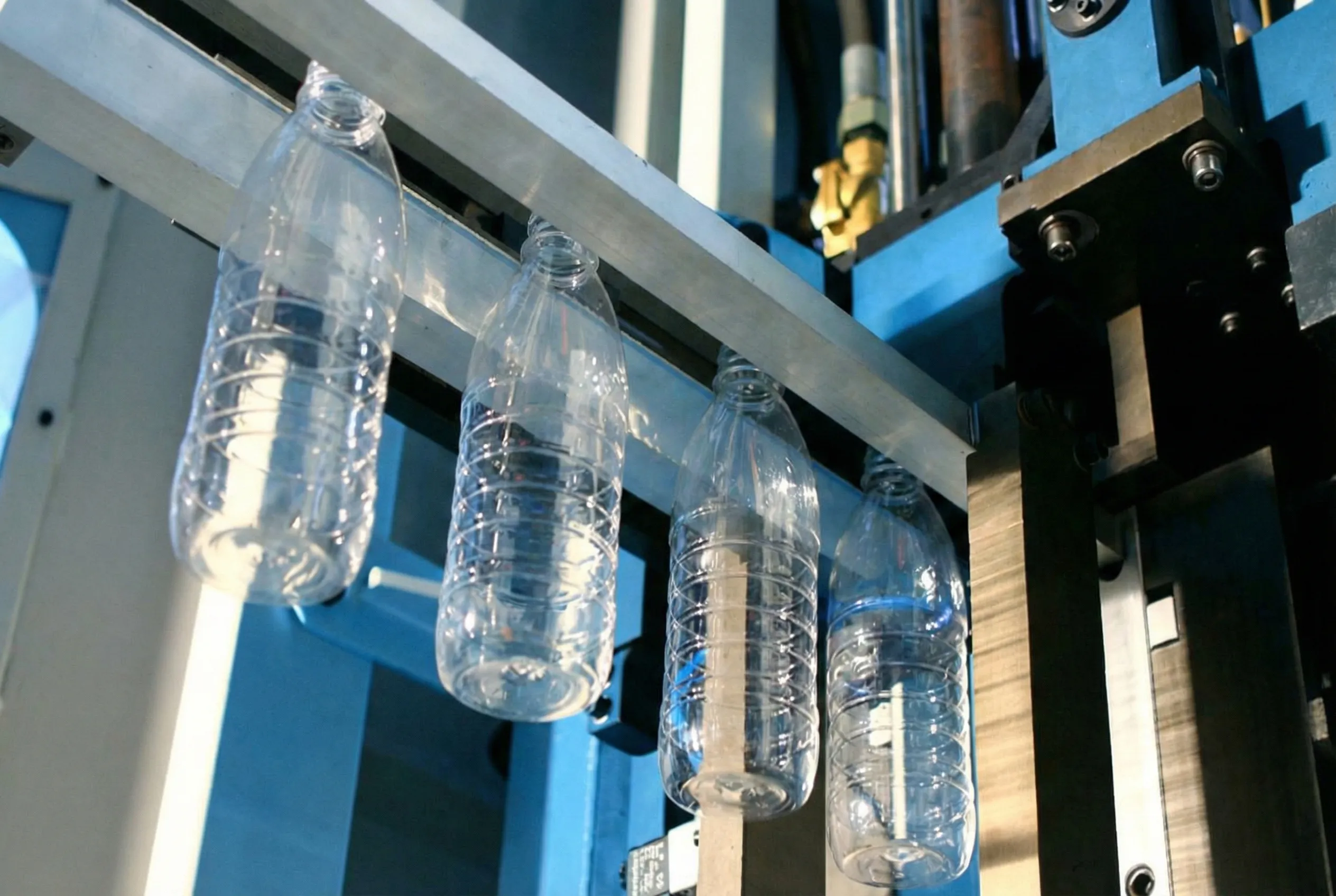
De injection stretch blow molding process transforms plastic resin — most commonly PET, PP, or HDPE — into finished hollow containers in a series of precisely coordinated stages. In the injection phase, molten polymer is injected into a preform mold to form a test-tube-shaped preform. This preform is then thermally conditioned to the optimal stretch temperature before being transferred to the blow station, where a stretch rod mechanically elongates it axially while high-pressure air inflates it radially to conform to the final bottle cavity shape.
What distinguishes single-stage from two-stage processes is that the preform never fully cools between injection and blowing — the retained latent heat from injection is used directly to condition the preform. This makes the single-stage approach highly energy-efficient and ideal for complex bottle geometries with narrow necks or precise wall thickness distributions.
The machine’s four primary systems — the injection unit, the conditioning/transfer unit, the blow unit, and the hydraulic/pneumatic drive system — must operate in flawless synchronization. Any deviation in timing, temperature, or pressure within any one of these systems will propagate directly as a measurable defect in the finished product, making precise and consistent maintenance critical to quality assurance.
Building a Robust Preventive Maintenance Schedule
A structured PM program is the single most impactful investment you can make in machine longevity.
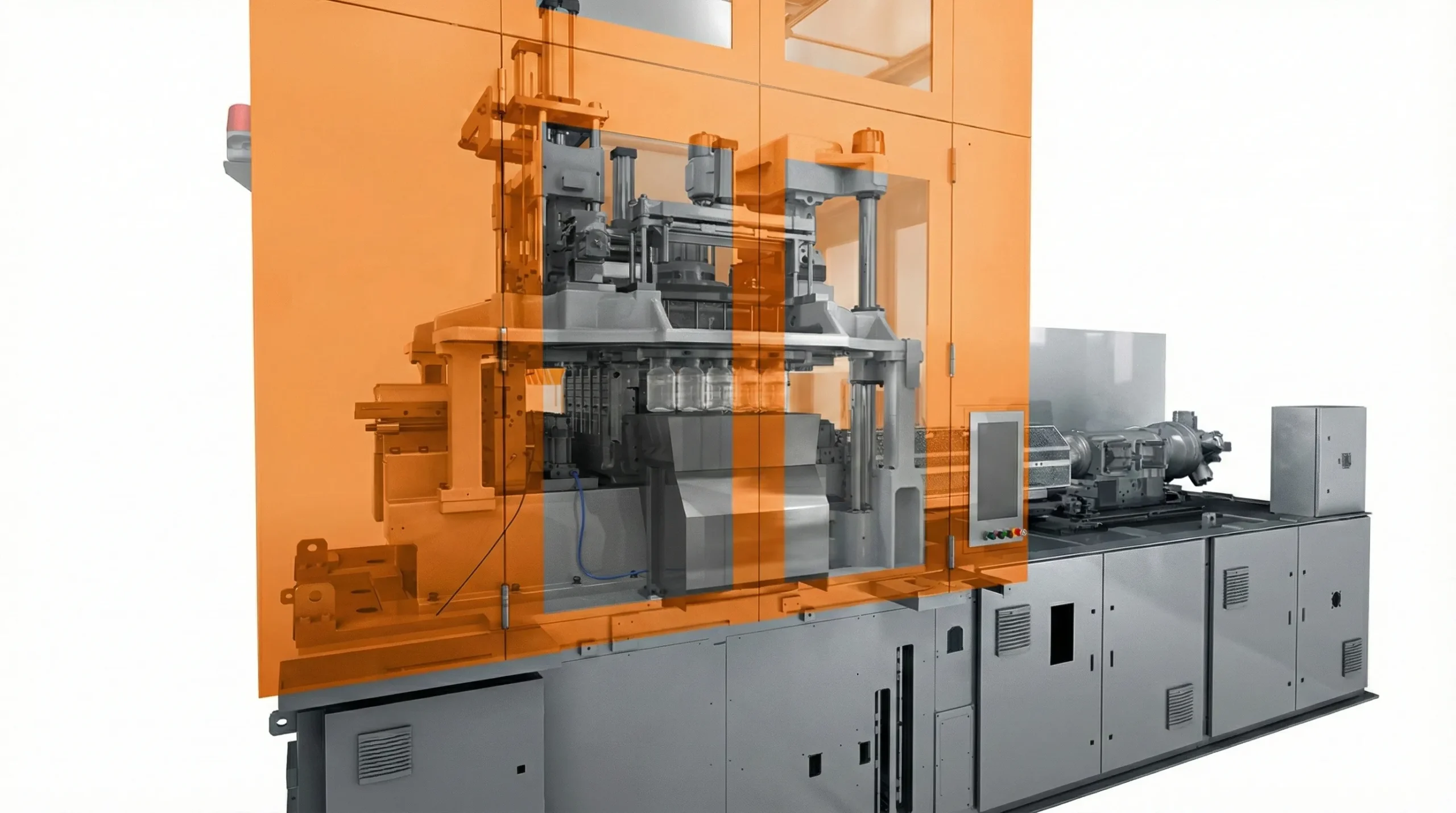
For a eentraps spuitgiet-rekblaasvormmachine, the all-in-one architecture means that injection tooling, thermal conditioning hardware, stretch rods, blow molds, and hydraulic drive systems are all housed within a single integrated frame. This concentration of critical subsystems makes it especially important to follow a tiered maintenance schedule that addresses each subsystem on the appropriate interval — daily, weekly, monthly, and annually.
🗓️ Daily Maintenance Checklist (15–20 Minutes Per Shift)
Daily inspections must be completed at the start of each production shift. Their purpose is to catch deviations before they cascade into stoppages or quality failures.
- Inspect hydraulic oil level and check for visible leaks around all cylinders, hoses, and fittings
- Verify cooling water flow rates and measure inlet/outlet temperature differential across each mold circuit
- Check compressed air pressure gauges — confirm both pre-blow and high-pressure blow circuit pressures are within setpoint
- Confirm barrel and hot runner temperature set points versus actual readings on the HMI; investigate any zone exceeding ±3°C deviation
- Inspect stretch rods visually for straightness, surface scratches, and secure end-fitting fastening
- Check the preform transfer system (index plate or robot arm) for smooth, vibration-free operation and correct timing
- Examine take-out gripper fingers and discharge conveyor for wear, misalignment, or accumulated resin flash
- Review the prior shift’s alarm log on the machine HMI and investigate any recurring fault codes
- Check hopper desiccant dryer dew point display — PET resin must be dried to ≤ −40 °C dew point before processing to avoid hydrolytic degradation
📅 Weekly Maintenance Tasks
- Lubricate all tie bars, toggle joints, guide rails, and linear bearings with the manufacturer-recommended grease specification
- Inspect the electrical cabinet — look for unusual heat signatures, condensation on terminals, or loose connections; re-torque any suspect terminals
- Clean mold parting lines and cavity venting slots with approved solvent; inspect surfaces for carbon deposit buildup
- Check the hydraulic filter differential pressure indicator — replace the filter element if it reads in the warning zone
- Inspect all O-rings on blow nozzles and seal seats; replace any showing flattening, cracking, or extrusion damage
- Verify injection screw back-pressure setpoint against actual melt cushion consistency — shot-to-shot cushion variation above ±2 mm indicates screw or check-ring wear
- Clean the barrel hopper throat zone and inspect hopper magnets for metallic contamination particles
- Test all safety gate interlocks, emergency stop circuits, and light curtains to confirm correct operation
🔧 Monthly Maintenance Tasks
- Perform a full hydraulic oil analysis — check viscosity index, contamination particle count (ISO 4406), and water content; discard and replace if outside specification
- Inspect all hydraulic hoses for abrasion, blistering, kinked sections, and coupling condition; replace any suspect hoses proactively
- Check injection platen parallelism with a precision dial gauge — platens must be within 0.05 mm over the full support length
- Measure barrel bore wear using a calibrated bore gauge at each injection zone; compare measured values against the OEM-specified wear limit table
- Inspect the hot runner manifold — measure each heater zone’s power draw and compare to rated values; check thermocouple continuity and resistance
- Clean and re-grease all robot arm linear guides, ballscrews, and pivot bearings per the OEM lubrication chart
- Check servo motor encoder cable connections and clean motor heat sink fins and cooling fan blades
- Inspect blow mold cavity surfaces under 10× magnification for stress cracking, corrosion pitting, seal groove wear, and parting line damage
🔩 Annual Major Overhaul
- Complete hydraulic system fluid flush and full replacement with fresh, filtered fluid meeting the OEM viscosity and additive specification
- Pull the injection screw and barrel for visual inspection, dimensional measurement using bore and flight gauges, and professional honing if required
- Replace all hydraulic cylinder seals; carefully inspect rod surface finish for pitting and chrome delamination that would accelerate seal wear
- Overhaul the clamp unit — measure tie bar elongation under load and replace any worn or cracked tie bar nuts and half-nuts
- Replace all temperature controller thermocouples and PID modules showing calibration drift greater than ±2°C from a calibrated reference
- Perform a comprehensive electrical panel inspection: torque all terminal blocks, replace discolored or cracked wiring insulation, verify grounding continuity to frame
- Back up the complete PLC program, all PID temperature profiles, and the full recipe library to at least two separate external storage devices
- Full calibration of injection pressure transducers, mold cavity pressure sensors, and all linear position encoders against certified reference standards
Maintaining Key Machine Components in Depth
Deep-dive technical guidance for every critical subsystem in your ISBM machine.
Injection Barrel & Screw
The plasticizing unit is the thermodynamic core of the machine. Screw wear typically results from abrasive fillers, incorrect back-pressure settings, or inadequate melt-film lubrication. For PET processing, screw compression zone geometry is critical; worn flights reduce melt homogeneity and cause inconsistent preform wall thickness. Monitor cushion size shot-to-shot — variation greater than ±2 mm indicates screw or check-ring wear and demands immediate investigation. Use only manufacturer-approved purge compounds when changing resin grades to prevent carbonized deposits forming in the screw root channels, which cause black spec contamination in preforms.
Hot Runner System
The hot runner manifold distributes melt from the injection barrel to each preform cavity with zero waste. Heater failures, thermocouple calibration drift, and valve gate seat erosion are the most frequently encountered issues. Check each zone’s actual power draw regularly — a heater drawing significantly less current than its rated value is beginning to fail. Leaks at the manifold-to-nozzle interface produce carbon streaks in preforms. Always torque manifold assembly bolts to the specified value at operating temperature, as thermal expansion changes the clamping force needed to maintain a leak-free joint.
Stretch Rod Assembly
The stretch rod is among the highest-wear items in the machine, operating at 4,000–12,000 strokes per hour depending on cavitation and cycle time. Inspect the rod tip contact face and cylindrical body for surface damage after every 500,000 cycles. A bent stretch rod produces off-center bottle bases and uneven wall thickness that no temperature or pressure adjustment can correct — replace the rod at the first confirmed deviation. The rod guide bushings must also be replaced at OEM-specified intervals, as bushing wear directly compromises the rod’s straightness during the stretching stroke.
Cooling Water Circuit
Effective mold cooling is the primary determinant of cycle time and bottle dimensional stability. Scale buildup on cooling channel walls acts as thermal insulation, progressively degrading heat transfer. For PET processing, keep water hardness below 150 ppm and pH between 7.0–8.5 with continuous chemical dosing. Periodically flush all mold cooling circuits with descaling solution and verify individual circuit flow rates against the original commissioning baseline — a blocked circuit creates hot spots and bottle paneling defects that are routinely misdiagnosed as temperature control faults.
Hydraulic Drive System
The hydraulic system drives clamping, injection, and all transfer movements. Contaminated hydraulic oil is the leading cause of premature proportional valve and pump failure. Always use the OEM-specified viscosity grade — substituting a lower viscosity to reduce cost causes pump cavitation and accelerated servo valve spool wear. Install a continuous inline particle counter if your production volume justifies it. Well-maintained hydraulic fluid extends pump service life by 2–3 times and represents the highest ROI maintenance measure available on any hydraulic ISBM platform.
High-Pressure Blow Air System
High-pressure blow air — typically 25–40 bar — demands clean, oil-free, dry compressed air. Install coalescing filters before the machine’s air inlet and replace elements on schedule. Oil mist contamination from compressors coats cavity surfaces, reducing mold release and causing surface defects on bottles. The blow valve block is a high-cycle wear component; inspect seat faces and dynamic seals at each mold change. Monitor the pressure rise trace on the HMI blow pressure graph — deviations from the baseline commissioning trace are among the most sensitive early indicators of valve wear or circuit restriction.
Comprehensive Troubleshooting Reference Guide
Systematic fault diagnosis — from bottle surface defects to hydraulic system alarms.
Effective troubleshooting demands strict discipline. The most common error is adjusting multiple parameters simultaneously — this makes it statistically impossible to identify the true root cause of any defect. The correct protocol is to change one variable per diagnostic cycle, run a minimum of one full production sequence to assess the effect, and document every change and result in a structured fault log. The reference table below covers the most frequently encountered defects and alarms, their probable causes, and recommended corrective actions based on engineering first principles.
Golden Rule of ISBM Fault Diagnosis
Never make more than one process change per diagnostic cycle. The fastest path to resolving any defect is rigorous variable isolation — change a single parameter, produce a measured sample, evaluate and record the result, then decide the next step. Multi-variable changes multiply diagnostic time exponentially and frequently introduce secondary problems that obscure the original fault.
| Defect / Fault | Probable Cause(s) | Corrective Action |
|---|---|---|
| Hazy / Cloudy Preform | Moisture > 50 ppm IV in resin; dew point failure; excessive barrel residence time | Verify dryer dew point ≤ −40°C; reduce barrel temp; check residence time; purge old resin |
| Uneven Preform Wall | Unbalanced hot runner flow; worn gate insert; offset stretch rod; platen parallelism error | Balance hot runner; replace gate; inspect rod alignment; measure platen parallelism |
| Off-Center Bottle Base | Bent or misaligned stretch rod; guide bushing wear; non-uniform preform temperature | Replace stretch rod and bushing; re-center preform in blow cavity; profile preform temperature |
| Bottle Paneling / Flat Spots | Low blow pressure; blocked cooling circuit; premature mold open; melt too hot | Increase blow pressure; flush cooling channels; extend blow time; reduce melt temperature |
| Flash at Parting Line | Insufficient clamp force; worn parting line surfaces; contamination on mold face | Increase clamp tonnage; clean and re-lap parting line; inspect mold for mechanical damage |
| Neck Ring Deformation | Excessive injection pressure; cooling deficiency in neck core; worn neck cavity insert | Reduce injection pressure; improve neck zone cooling flow; replace neck cavity insert |
| Short Shot / Incomplete Preform | Insufficient injection volume; cold gate; blocked runner; degraded resin viscosity | Increase shot size or velocity; raise hot runner setpoint; purge runner system; check IV |
| Stress Whitening | Preform temperature below stretch window; excessive stretch ratio; non-uniform heating | Raise conditioning temperature; reduce stretch speed; optimize temperature zone profile |
| Hydraulic Overpressure Alarm | Blocked valve or cylinder; contaminated oil; pump cavitation; mechanical binding | Check oil level and viscosity; inspect valve spool; verify no mechanical obstruction |
| Cycle Time Creep | Hydraulic oil overheating; reduced pump output volume; degraded mold cooling efficiency | Service oil cooler; clean cooling water heat exchanger; verify pump pressure and flow output |
| Preform Sticking in Cavity | Worn or damaged cavity surface finish; insufficient draft angle; over-cooling; contamination | Polish cavity surface; clean and apply release agent; adjust cooling time; inspect draft |
Advanced Technique: Preform Temperature Profiling
One of the most powerful diagnostic tools available to an ISBM technician is the preform surface temperature profile. Using an infrared thermometer or — preferably — a thermal imaging camera, map the temperature distribution across the preform surface immediately after it exits the conditioning station. Any asymmetry or localized hot spot in this thermal map directly predicts the corresponding wall thickness variation in the blown bottle. A hot spot on the preform shoulder, for instance, will always produce a thin, potentially weak shoulder zone in the finished container.
The injection fill balance between cavities — measurable via cavity pressure sensors or simply by weighing individual preforms from each cavity position — provides direct, quantitative information about hot runner performance. A cavity consistently producing lighter preforms than the system average indicates a restricted gate, a failed heater, or a thermocouple reading incorrectly low.
For hydraulic system diagnosis, capturing a pressure-versus-time trace from the machine’s HMI data logger during a normal production cycle and comparing it to the baseline trace from commissioning is among the most effective approaches. Delayed pressure rise, pressure spikes, or inability to sustain target pressure each point to specific hydraulic components — pump, proportional valve, accumulator, or cylinder — for targeted investigation rather than speculative parts replacement.
Sourcing Parts, Upgrades & Machine Replacement
Knowing when to repair, when to upgrade, and when to replace is a critical business decision.
When Replacement Outperforms Repair
Many manufacturers operating legacy equipment have found significant productivity and energy efficiency gains through the vervanging van Aoki spuitgiet-rekblaasvormmachines and other older-generation platforms with modern servo-driven equivalents. The financial case for replacement versus repair becomes compelling when: annual maintenance costs consistently exceed 15% of the machine’s current replacement value; critical spare parts are no longer stocked or manufactured by the original OEM; or energy consumption data shows inefficiency exceeding 20% compared to current-generation platforms with servo-electric drive.
Modern machines feature all-electric servo clamping (eliminating hydraulic oil and its maintenance overhead entirely), full servo-electric injection, and real-time cavity pressure monitoring as standard. These translate to measurably lower energy costs, improved process consistency, and dramatically reduced maintenance labor over the machine’s operational lifetime.
Evaluating Manufacturing Partners
When selecting an IBM-machinefabrikant, total cost of ownership is a far more meaningful criterion than purchase price alone. TCO is determined by spare parts availability and cost, technical support quality and response time, documented machine MTBF performance, and the supplier’s experience with your specific application — PET water bottles, PP wide-mouth containers, or pharmaceutical-grade specialty packaging each have distinct process requirements.
A trustworthy leverancier van IBM-spuitgietmachines will provide comprehensive installation support, structured operator training, detailed process documentation, and guaranteed spare parts availability for a defined minimum period — typically 10–15 years post-delivery. These commitments are as critical to evaluate as the machine’s published technical specifications.
🔴 Key Indicators Your ISBM Machine Needs Replacement
Safety Best Practices During Maintenance Operations
No production target justifies compromising the safety of the technician performing the work.
ISBM machines present multiple concurrent hazard categories simultaneously: high-temperature surfaces (barrel operating temperatures typically 265–295°C for PET), high-pressure hydraulic circuits up to 200 bar, high-pressure pneumatic circuits up to 40 bar, high-voltage electrical systems including servo drives and barrel heaters, and fast-moving mechanical components with significant kinetic energy. Any maintenance procedure requiring entry into the machine’s safety envelope — defined by the physical guards and light curtains — must follow a complete and verified Lockout/Tagout (LOTO) procedure before work begins.
Lockout / Tagout (LOTO)
De-energize and physically lock out all electrical, hydraulic, and pneumatic energy sources before any maintenance access. Verify true zero energy state with a calibrated test instrument before entry.
Personal Protective Equipment
Wear heat-resistant gloves rated for barrel and hot runner work, safety glasses at all times on the machine floor, and full face shields when purging material or working near hydraulic fittings under pressure.
Documented Work Procedures
All maintenance activities must be performed to documented, approved procedures with a completed Job Safety Analysis (JSA). No ad-hoc or unauthorized maintenance should ever be permitted on ISBM equipment.
When working on the hot runner or barrel assembly, allow a minimum of 30 minutes after power-down for surface temperatures to fall below safe working thresholds (verified with a surface thermometer). Always purge residual plastic from the barrel before breaking the screw-to-barrel flange connection. For hydraulic maintenance, bleed all accumulators and verify zero circuit pressure with a calibrated analog gauge — never assume any hydraulic circuit is depressurized because the pump motor is off. Pneumatic circuits also store significant energy in receiver tanks that must be vented to atmosphere and confirmed at zero pressure before any fitting is disturbed. These are non-negotiable minimum safety requirements; they apply equally to experienced and new technicians on every occasion without exception.
When to Contact Your Machine Manufacturer Directly
While this guide addresses the vast majority of maintenance and troubleshooting scenarios encountered in day-to-day operation, there are situations where direct OEM support is not merely helpful but essential. If you are researching an IBM-machine te koop or comparing leading fabrikanten van spuitrekblaasvormmachines for your next capital project, after-sales capability is a defining selection criterion.
Contact your OEM immediately when experiencing: repeated faults that do not respond to the corrective actions in this guide; mechanical failures involving the machine frame, tie bars, or platen guide system; servo drive or PLC failures triggering safety shutdowns; or any situation where the machine has suffered physical damage from a tooling crash. Self-repairing servo drives or safety PLC hardware without OEM authorization voids warranties and can introduce unrecorded safety-critical calibration errors.
Ever-Power ISBM Machine Product Range
Industry-leading injection stretch blow molding machines — built to perform, engineered to last.
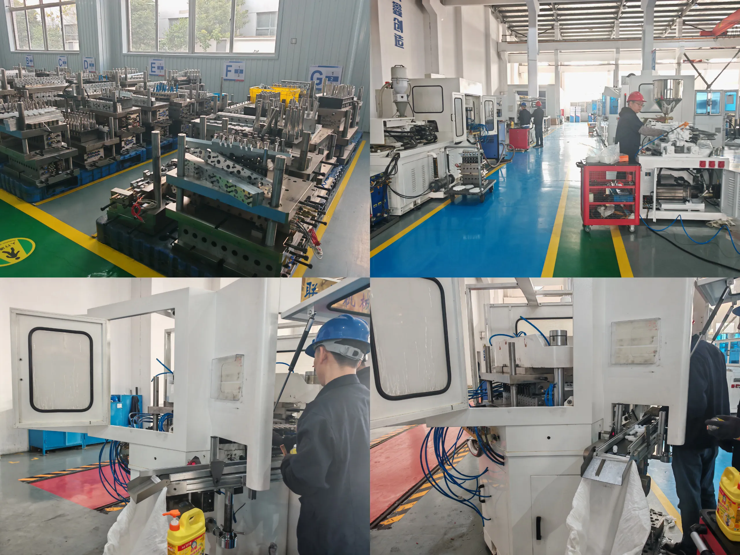
As a dedicated ISBM machinefabrikant, Ever-Power designs and builds a comprehensive range of injection stretch blow molding machines engineered for reliability, energy efficiency, and superior bottle quality. Every machine we deliver is supported by a comprehensive spare parts stocking program, factory-trained service engineers available globally, and documented process engineering assistance — giving your production team everything needed to achieve maximum OEE from initial commissioning throughout the machine’s full operational lifetime.
2-Station ISBM Machine
Compact and highly efficient two-station platform designed for small-to-medium production runs. Features rapid mold changeover, servo-controlled clamping, and full PET/PP/HDPE material compatibility. Ideal for cosmetic bottles, pharmaceutical containers, and specialty packaging applications where flexibility and footprint efficiency are priorities.
3-Station ISBM Machine
The industry-standard three-station configuration — injection, conditioning, and blow — delivering the optimal balance of output rate and production flexibility. Suitable for PET water bottles, juice containers, and wide-mouth food jars from 50 ml to 5 L. Available in multiple clamp force configurations to match your cavity count and product weight requirements.
4-Station ISBM Machine
High-output four-station platform with two independent thermal conditioning zones for maximum preform temperature control precision. The additional station enables complex bottle profiles with demanding specifications that require tighter thermal windows. Best suited for high-volume PET production lines and technically challenging container geometries with asymmetric heating requirements.
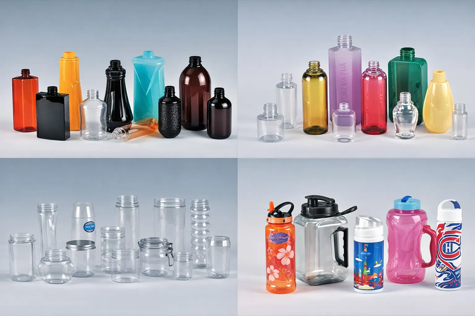
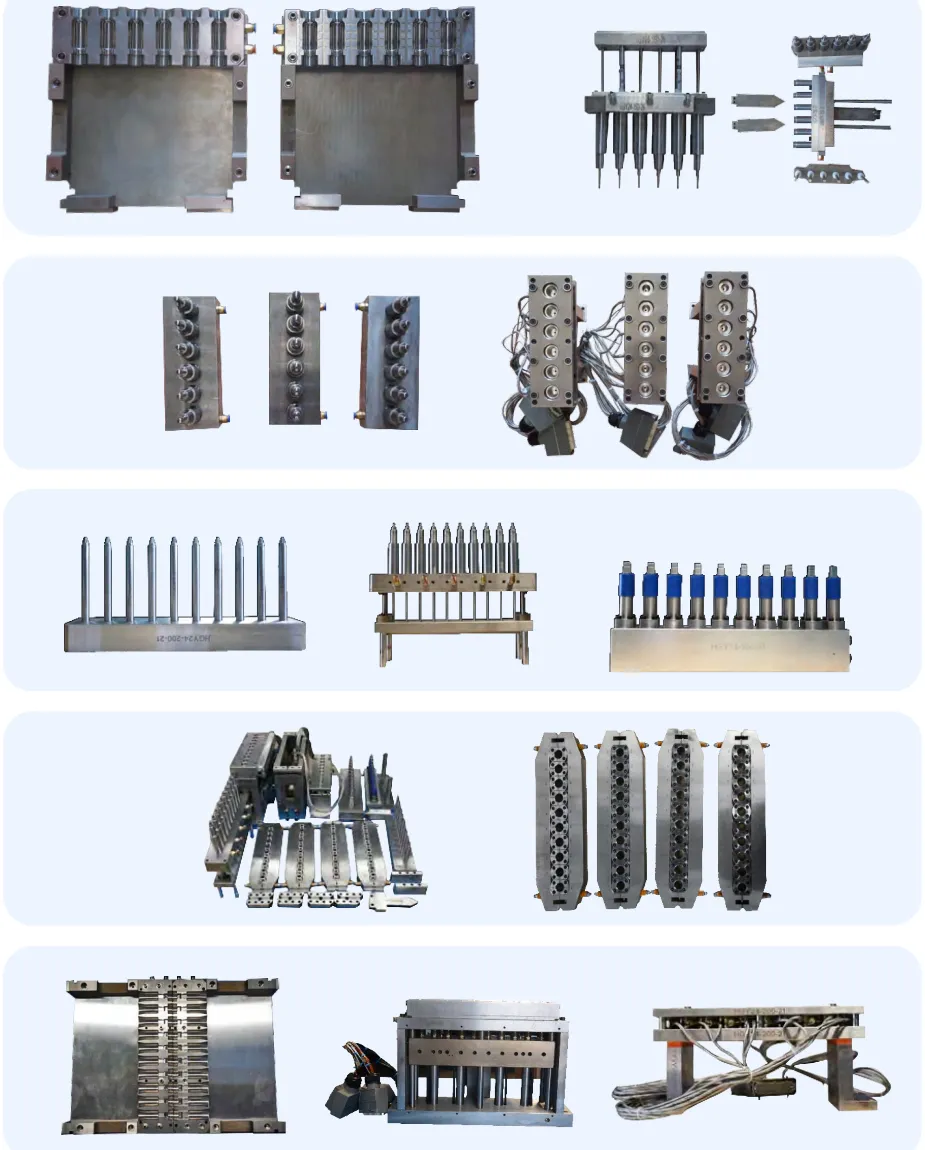
ISBM Preform & Blow Molds
Precision-machined preform molds, blow molds, and neck ring tooling manufactured to tight dimensional tolerances for optimal bottle quality and long tool life. Available in P20 hardened steel, 420 stainless steel, and aircraft-grade aluminum alloy to match your production volume and material. Full design-to-delivery service including 3D bottle design, mold flow analysis, and on-machine qualification support from our application engineers.
Spare Parts & After-Sales Support
Comprehensive spare parts stocking program covering all wear items, hydraulic components, electrical consumables, and critical assemblies for the complete Ever-Power machine range. Same-day dispatch for stock items on critical components. Factory-trained service engineers available globally for on-site commissioning, structured operator and maintenance training programs, preventive maintenance contracts, and emergency breakdown response. Guaranteed parts availability for a minimum of 12 years post machine delivery.
Ready to Upgrade, Expand, or Source a New Machine?
Share your bottle application details, annual production volume targets, and material requirements with our engineering team. We will recommend the optimal machine configuration, cavity count, and mold specification to meet your exact production and quality objectives.


