The Hidden Cost of a 2 mm Gate Deviation
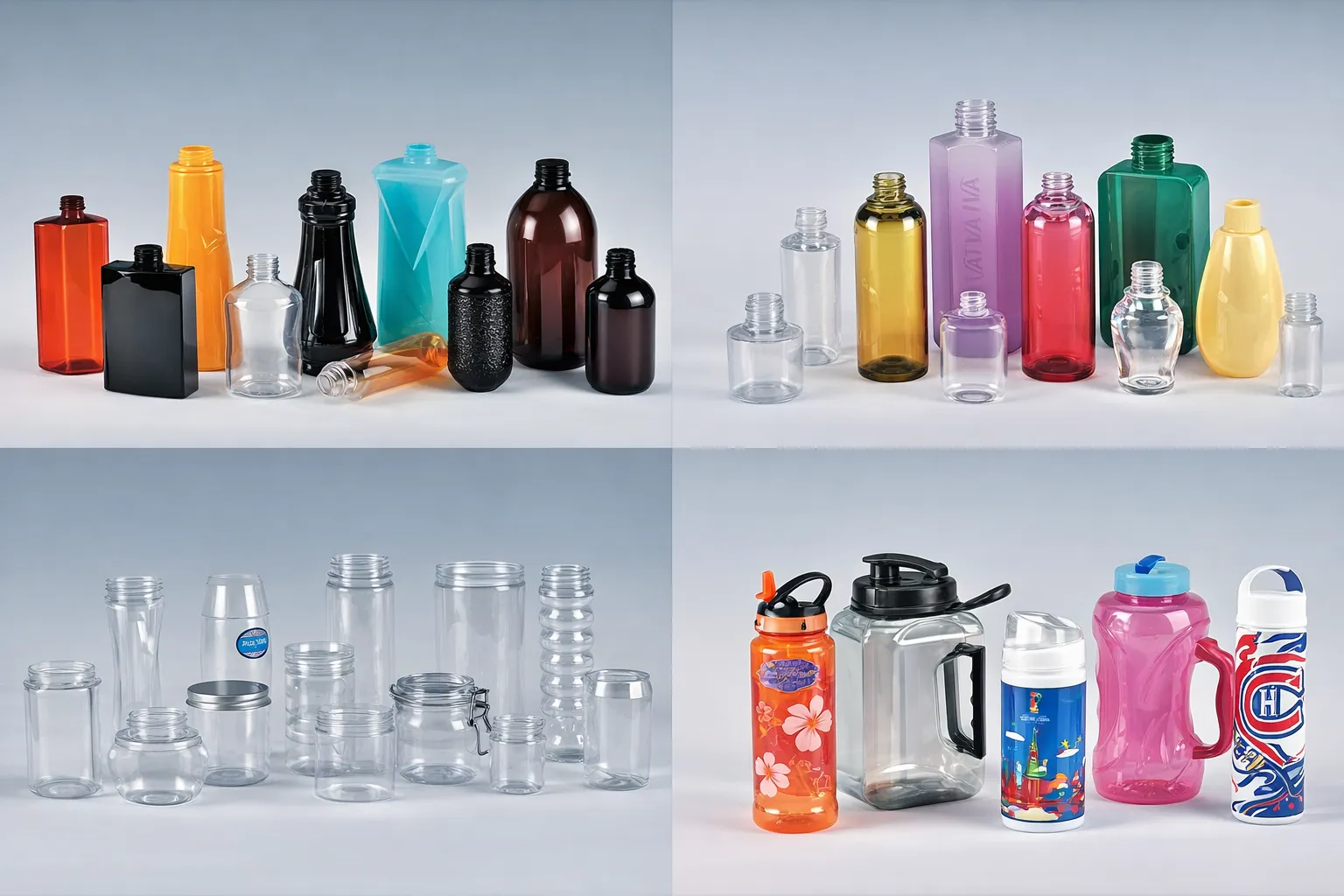
Off-center gates in stretch blow molded bottles represent one of the most persistent yet underestimated quality issues in the PET container manufacturing industry. What appears at first glance to be a minor cosmetic flaw — the residual gate point sitting even slightly off the bottle base’s center — sets in motion a chain of technical consequences that can undermine product integrity, brand appearance, and line efficiency in ways that are not always immediately visible on the production floor.
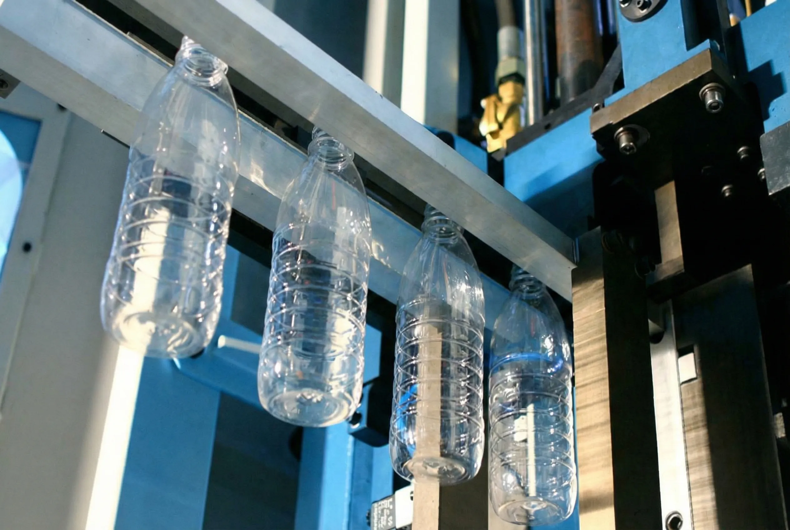
The gate is the remnant of the injection point left on the preform base after the sprue is removed. During the injection stretch blow molding process, this gate position transfers to the finished bottle and should sit at the exact geometric center of the base. When it drifts — even by two or three millimeters — the effects extend far beyond appearance.
In pressurized applications such as carbonated beverages, an off-center gate can reduce burst pressure performance by 15 to 25 percent. In hot-fill applications, asymmetric stress distribution accelerates deformation under heat. For retail-ready containers, the resulting wall thickness variation causes label wrap problems, unstable rotation on filling conveyors, and elevated rejection rates at automated optical inspection systems. Understanding the root causes — and addressing them systematically — is essential for any operation that depends on consistent bottle quality.
What Exactly Is an Off-Center Gate?
Before diagnosing root causes, it is essential to understand precisely what is being measured and why the deviation matters in real-world production contexts.
Gate Definition
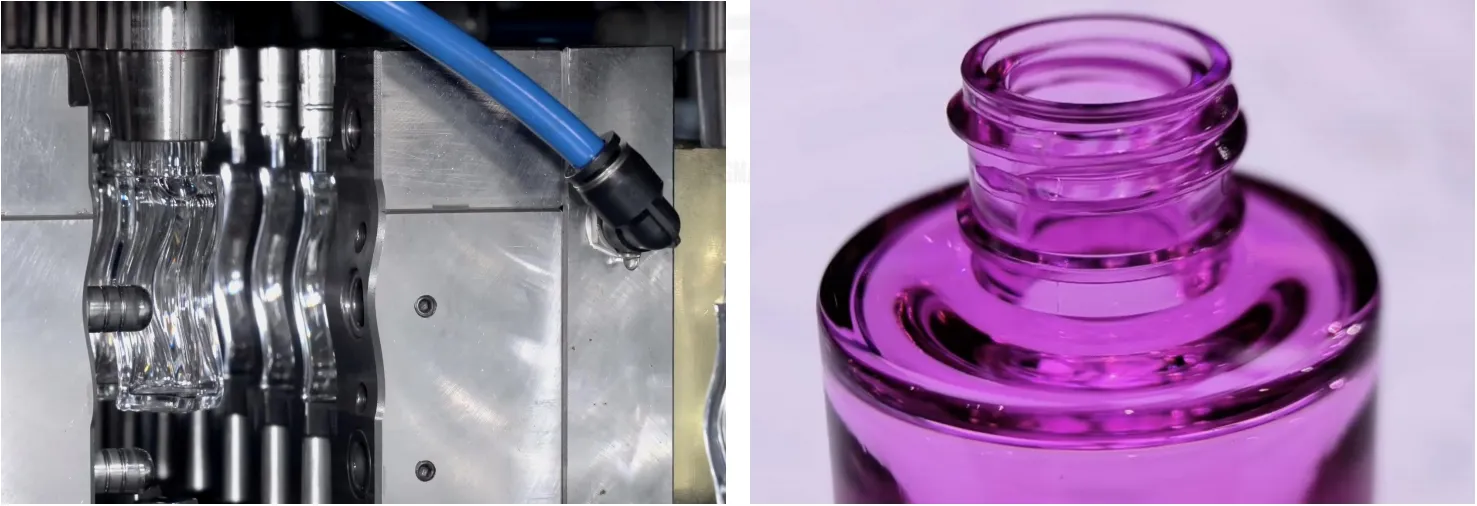
The gate is the residual material mark on the preform base where molten PET was injected into the cavity. In the finished bottle, this becomes a small protrusion or circle at the base center — the anchor point from which the entire stretching process is referenced during blow molding.
Measurement Standard
Gate offset is measured as the linear distance from the gate center point to the bottle base’s geometric center — expressed as X-Y coordinates. Industry tolerance specifications typically permit a maximum deviation of 0.3–0.8 mm depending on application. Deviations above 1.5 mm are universally classified as critical defects requiring immediate corrective action.
Performance Impact
A gate offset creates asymmetric wall thickness distribution throughout the bottle body. The thinner regions become stress concentration zones under mechanical loading, reducing top-load strength, drop-impact resistance, and internal pressure ratings — all of which are contractual performance parameters for most commercial packaging applications.
Industry Insight: On a filling line producing 8,000 bottles per hour, a consistent gate offset that pushes rejection rates from 0.5% to 3% translates to roughly 200 additional rejected bottles per hour. Over a 16-hour production day, that is 3,200 wasted containers — before accounting for the downstream impact on filler uptime and customer complaints.
The Six Primary Causes of Off-Center Gates
In most production scenarios, off-center gates are not caused by a single isolated variable. They result from compounding factors across process parameters, equipment condition, mold geometry, and material quality — each amplifying the others.
1. Preform Temperature Non-Uniformity
Temperature distribution within the preform wall is the single most influential variable governing gate position in the finished bottle. When the circumferential temperature profile of the preform body is not perfectly uniform — a condition referred to as thermal asymmetry or “hot spot” — the subsequent stretch blow cycle amplifies that asymmetry into measurable gate deviation. The physics of this are straightforward: during the blow phase, PET follows the path of least resistance, and a preform wall section that is even 3–5°C warmer than the surrounding material will stretch faster and further, pulling the gate point toward the heat-affected zone.
Temperature non-uniformity in preforms originates from several sources: inconsistent infrared lamp output across the oven array, uneven lamp-to-preform spacing caused by spindle wear or misalignment, inadequate preform rotation speed during the heating phase, and air draft interference from HVAC systems or open factory doors disrupting the thermal boundary layer within the oven zone.
Lamp degradation is particularly problematic because it is gradual and difficult to detect without proactive measurement. As lamp output decreases over time, operators tend to compensate by raising overall oven temperature — which masks individual lamp inconsistency while increasing the overall thermal gradient risk. Regular infrared profiling of each individual lamp at defined intervals is the only reliable way to catch developing asymmetry before it reaches production-impacting severity.
🔬 Diagnostic Indicators
- →Gate consistently migrates in the same radial direction across all or most cavities
- →Wall thickness measurement shows ≥0.15 mm side-to-side difference
- →Gate offset worsens progressively as oven set-point temperature increases
- →Infrared thermal survey reveals asymmetric heat band on preform surface
- →Problem is cavity-independent — affects all cavities uniformly at same offset magnitude
2. Stretch Rod Misalignment or Mechanical Wear
The stretch rod serves a dual mechanical function during the blow cycle: it physically contacts the preform base to initiate axial elongation, and its contact point functions as the anchor from which radial expansion propagates outward. If the stretch rod is not perfectly coaxial with the blow mold cavity axis, the contact point will land off-center on the preform base — and every bottle blown in that cavity will carry the resulting gate offset as a direct mechanical consequence.
Even sub-millimeter rod misalignment — typically caused by guide bushing wear, rod body fatigue bending, carriage mounting drift, or debris accumulation in the guidance system — is sufficient to produce visible gate deviation. In multi-cavity machines, rod alignment must be independently verified and adjusted per cavity, since wear rates differ across blow stations depending on their position in the machine and variation in clamping force distribution.
This problem becomes particularly acute in machines operating above 50,000 cumulative hours without scheduled guide component replacement. Eccentric bushing wear develops slowly and silently; operators rarely notice the progressive gate offset deterioration until it crosses a rejection threshold. Scheduling stretch rod runout measurement at defined PM intervals — not merely checking the rod visually — is the only proactive defense.
When evaluating a enostopenjski stroj za brizganje z raztezanjem in pihanjem, technically informed buyers specifically examine the stretch rod guidance system’s engineering design, published TIR specification, and availability of certified replacement components — these factors directly predict long-term gate quality performance.

3. Blow Mold Cavity Eccentricity and Progressive Wear
Even when stretch rod alignment is correct and preform temperature is perfectly uniform, an eccentric blow mold cavity will still produce off-center gates on every bottle. Mold cavity eccentricity describes a condition where the cavity’s geometric axis does not coincide with the machine’s blow axis — the mold itself is slightly tilted, shifted, or misoriented relative to the stretch rod travel path.
This condition arises from several sources: initial manufacturing tolerances in the mold set, improper installation and clamping during mold change, differential thermal expansion during production warm-up (which can shift mold components relative to each other), or progressive wear at mold parting surfaces, split lines, and clamping interfaces. When a reputable dobavitelj strojev za brizganje kalupov isbm manufacturers molds to tight concentricity tolerances with documented CMM inspection reports, this risk is minimized at the outset — but proper machine installation, temperature management, and maintenance protocols remain essential to sustaining that precision through the mold’s operational life.
The insidious nature of mold wear-induced gate offset is its gradual development. Production engineers who monitor gate position only through exception reporting — reacting when a bottle fails an inspection check — will consistently miss the early-stage drift that preventive intervention could resolve at minimal cost and disruption.
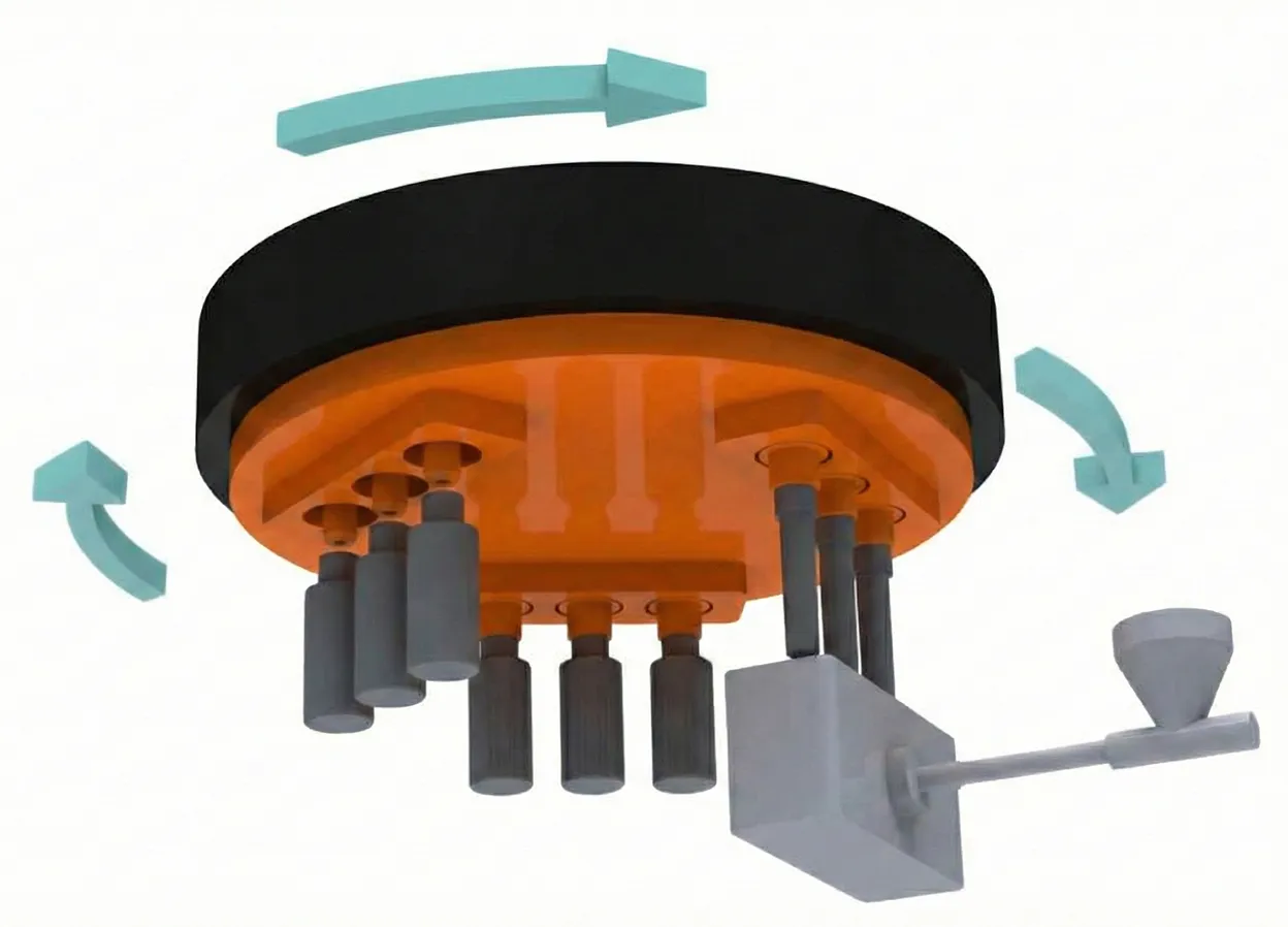
4. Blow Air Delivery Asymmetry and Timing Errors
The pneumatic system that delivers compressed blow air through the stretch rod or a dedicated blow nozzle must supply air coaxially with the cavity axis. Any asymmetry in the air delivery path — caused by worn or bent air passage components, uneven valve seats, asymmetric flow channels within the stretch rod body, or pressure fluctuations from supply system irregularities — will cause the expanding PET bubble to initiate from an offset position. As the bubble grows, it carries the gate point with it, anchoring the finished bottle’s gate to an off-center position that is effectively impossible to correct after the fact.
The pre-blow phase is disproportionately critical. Pre-blow establishes the initial geometry of the expanding bubble before high-pressure blow locks the material against the mold cavity walls. Any asymmetry introduced in pre-blow is then magnified — not corrected — by the subsequent high-pressure stage. Monitoring pre-blow pressure waveforms per cavity, using a consistent and properly calibrated pressure curve profile, and protecting against any contamination of the blow air supply are foundational requirements for stable gate centering.
5. Preform Dimensional Inconsistency
The preform must meet tight dimensional specifications for consistent gate positioning in the finished bottle. Critical dimensions include preform gate vestige geometry, body wall thickness uniformity around the circumference, body ovality (roundness of the preform cross-section), and the concentricity of the thread finish relative to the body axis. Variations in any of these parameters affect how the preform distributes stretch forces during blowing and where the gate ultimately lands.
Gate vestige geometry deserves particular attention: if the gate on the preform is already off-center due to imbalanced injection runner design, excessive cavity-to-cavity IV variation within a hot runner system, or inconsistent sprue trimming operations, that pre-existing eccentricity will propagate directly to the finished bottle regardless of how precisely the blow machine is calibrated. Inspecting incoming preforms for gate concentricity should be a standard incoming quality control step.
Body wall thickness variation presents a subtler problem. Even when wall thickness appears uniform to manual gauging, variations in molecular crystallinity from the injection phase create invisible zones of differential stretch resistance. These zones — which may be associated with visible phenomena like tiger stripes, pearlescence, or flow marks — stretch preferentially during blow molding, disrupting symmetric material distribution and pulling the gate point toward the zone of lower crystallinity.
Sourcing preforms from external suppliers introduces additional quality variability unless robust supplier qualification programs, documented process specifications, and statistical incoming inspection protocols are in place and actively enforced.
6. PET Resin Quality and Moisture Content
PET resin intrinsic viscosity (IV) directly governs how the material flows during injection and how uniformly it stretches during blow. Lot-to-lot IV variation creates inconsistency in preform wall thickness distribution and in the material’s resistance to thinning during stretching. Higher IV material is stiffer and requires more energy to stretch to final wall thickness; lower IV material flows more readily but may fail to develop the biaxial orientation needed for adequate mechanical performance. Blending resin lots without verifying IV consistency is a known root cause of periodic gate offset events that appear random and are difficult to attribute without careful material traceability.
Moisture content is equally critical and more immediately problematic. PET resin that has not been adequately dried to below 50 ppm moisture content undergoes hydrolytic degradation during injection, reducing IV locally and creating weak spots within the preform wall. These degraded zones stretch faster than surrounding material during the blow cycle, pulling the gate point toward them and producing off-center gates that correlate with specific preform body positions. Maintaining PET at 160–180°C for a minimum of four to six hours in a dehumidifying dryer, and verifying moisture content with a Karl Fischer titration meter before use, is non-negotiable for reliable gate quality.
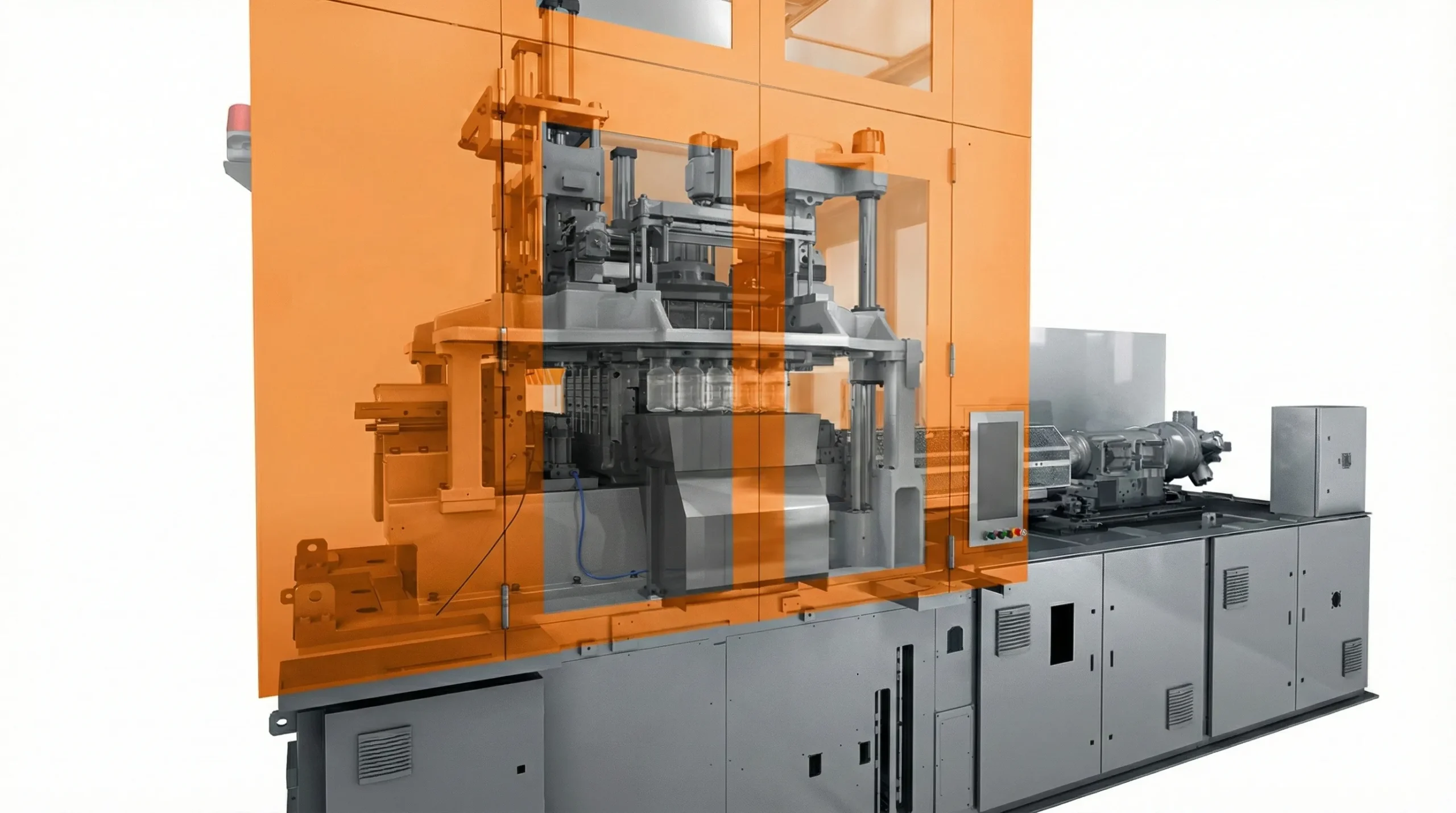
How Machine Architecture Influences Gate Quality
The mechanical architecture of the blow molding machine establishes the physical boundaries within which process optimization operates. No amount of process fine-tuning can fully compensate for fundamental machine design deficiencies.
Machine rigidity under clamping force is a foundational gate quality parameter that is frequently underestimated during equipment selection. When the blow mold closes, the clamping system must deliver symmetric, uniformly distributed force across all tie bars simultaneously. Machines with insufficient platen stiffness or unbalanced clamping systems allow mold halves to deflect asymmetrically under load, creating localized cavity eccentricity that produces gate offset specific to individual cavities under full production conditions — conditions that may not be replicable during factory acceptance testing at lower cycle rates.
A qualified proizvajalec strojev ISBM engineers machines with heavy-duty platen systems, precision-ground guide columns, and servo-driven stretch rod mechanisms specifically to provide the mechanical rigidity and repeatability foundation needed for consistent gate centering at high production speeds over long operational lifetimes.
Thermal management architecture also matters. Machines with truly independent heating zones per cavity — as opposed to shared zone designs where one controller governs multiple spindle positions — give operators the granular control needed to correct individual-cavity temperature profiles without disturbing neighboring cavities. This independence is essential for addressing cavity-specific gate offset caused by localized oven inconsistency.
⚙️ Key Machine Specifications for Gate Quality
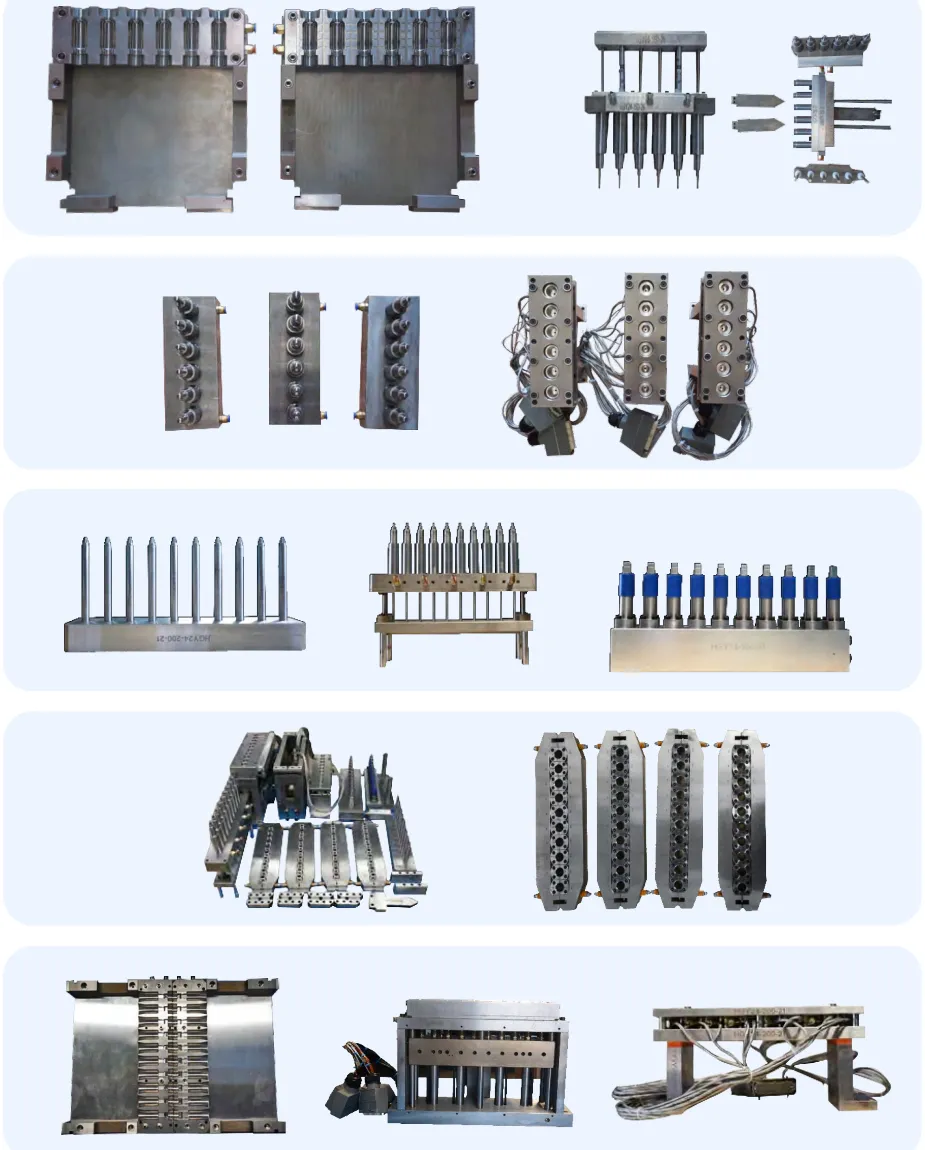
Mold Design Factors in Gate Centering
The blow mold’s engineering precision serves as the silent guardian of gate quality. Even with a well-maintained machine and carefully optimized process parameters, a poorly designed, improperly installed, or progressively worn mold set will produce off-center gates with a consistency that makes root cause attribution difficult without systematic elimination.
Critical mold design parameters affecting gate centering include: cavity-to-base-insert concentricity tolerances, base plug geometry and vent channel design, interlocking and locating precision between mold halves, cavity surface finish in the base area affecting material release dynamics, and the flatness and parallelism of mold mounting surfaces relative to machine platens.
The base insert — the removable mold component that forms the bottle base geometry — is particularly critical. Any eccentricity in base insert seating directly positions the cavity axis relative to the stretch rod contact point. A reliable dobavitelj strojev za brizganje kalupov isbm manufactures base inserts to sub-0.03 mm concentricity specifications, uses precision-fit locating features (H7/n6 interference fit standard), and provides full CMM dimensional inspection reports with each mold set delivered.
🔧 Mold Design Best Practices
- Base insert alignment: Precision locating dowels with H7/n6 fit — eliminates installation-variable eccentricity
- Cavity concentricity: Verify cavity axis to <0.03 mm TIR relative to mold mount centerline before acceptance
- Vent channel balance: Symmetric venting prevents localized pressure buildup that deflects the expanding bubble
- Parting line flatness: Maintain ≤0.01 mm flatness per 100 mm to prevent asymmetric mold breathing under clamp load
- Base surface finish: Mirror polish (Ra <0.04 μm) in base area reduces material drag effects during bottle ejection
💡 Pro Tip: Gate Trend Monitoring
Maintain a gate position trending chart per cavity across production runs. When any cavity’s rolling average gate offset exceeds 0.5 mm over a defined sample window, schedule that cavity for mold inspection proactively. Catching mold wear at the 0.5 mm stage typically requires only cleaning and minor adjustment; waiting until reject threshold is reached may require mold regrinding or component replacement at significantly higher cost and production impact.
A Four-Layer Prevention Strategy
Eliminating off-center gates requires a structured, multi-layer approach that addresses all potential root causes simultaneously. Chasing individual symptoms without a systematic framework yields temporary improvement at best.
Layer 1: Process Standardization
Develop and formally lock a “golden process recipe” for each product, covering oven temperature profile per zone, pre-blow pressure curve shape, high-pressure blow profile, stretch rod contact timing and speed, and blow exhaust timing. Any deviation from this locked recipe should require formal change authorization and gate position verification before resuming production quantity.
Verify that all critical parameters of the injection stretch blow molding process are confirmed at each production startup, following any maintenance intervention, and at minimum every two hours during running production for high-precision applications. Document these checks in a production log tied to quality records for each batch.
Layer 2: Preventive Maintenance Protocol
Establish a rigorous PM schedule covering: stretch rod alignment checks and bushing wear measurement (weekly), blow mold cavity centering verification (monthly), oven lamp intensity audit with replacement schedule (every 500 production hours), clamp force balance verification (quarterly), and preform transfer mechanism positional accuracy check (monthly).
Use precision measurement instruments including dial test indicators for runout measurement, calibrated IR cameras for preform temperature profiling, and coordinate measuring machine (CMM) inspection for mold geometry validation. These tools pay back their cost many times over in prevented defect events.
Layer 3: Statistical Process Control
Implement SPC monitoring for gate position measurements on each cavity independently. Collect X-Y gate offset coordinates at defined sampling intervals and plot on Individual-Moving Range (I-MR) control charts with 3-sigma control limits. The critical insight of SPC is that trend analysis — a cavity slowly but consistently drifting toward the control limit — is far more actionable than point-in-time exceedance events. Early detection allows preventive intervention before defect-level offsets occur.
Integrate wall thickness gauging, top-load compression testing, and internal pressure testing data into the same SPC framework. Correlating these downstream performance metrics with gate offset measurements provides the evidence base to set and justify appropriate gate centering specifications for each container design.
Layer 4: Operator Training and Knowledge Management
Process technicians must understand not only how to adjust parameters, but the physical reasoning behind each parameter’s effect on gate position. A trained operator who understands the cause-and-effect relationships — that a gate migrating consistently toward the 3 o’clock position points first to a cold oven zone at that radial position, or to the relevant cavity’s stretch rod runout — can diagnose and begin corrective action in minutes rather than hours.
Regular competency refreshers, written troubleshooting guides organized by symptom pattern, and structured escalation protocols ensure gate quality is managed proactively across shifts and during workforce transitions. Knowledge continuity is an asset that compounds over time when actively managed.
⚡ Quick Troubleshooting Reference: Gate Offset by Symptom Pattern
| Observed Symptom | Most Likely Root Cause | First Corrective Action |
|---|---|---|
| Same offset direction on ALL cavities | Oven temperature asymmetry or machine-level stretch rod misalignment | IR profile oven zones; check machine center axis perpendicularity |
| Offset on ONE specific cavity only | Cavity-level mold eccentricity or individual stretch rod TIR issue | Inspect that cavity’s mold alignment; measure stretch rod runout at that station |
| Random direction, random cavities | Incoming preform dimensional variation or resin quality issue | Audit incoming preform concentricity; verify resin drying records and IV certificates |
| Offset increasing steadily over production run | Thermal drift in oven zone or progressive mold wear during run | Log process stability data; schedule mold inspection and oven lamp measurement |
| Offset appears after maintenance shutdown | Component reinstallation error or misalignment during reassembly | Full alignment verification: stretch rod, mold mounting, preform transfer system |
Choosing an ISBM Machine That Delivers Gate Quality at Scale
Equipment selection is the long-term investment that defines the upper boundary of what your process can achieve. Here is what experienced procurement teams prioritize.
The landscape of proizvajalci strojev za brizganje in raztezanje z vdihavanjem spans premium-tier European and Japanese original equipment makers to increasingly capable Asian producers offering comparable — and in some specifications, superior — technical performance at substantially lower capital cost. The key distinction in machine evaluation lies in engineering specifications and documented production data, not brand legacy alone.
Many facilities operating aging Japanese equipment are now actively evaluating a zamenjava strojev za brizganje in raztezanje z vpihovanjem Aoki with modern alternatives that match or exceed original equipment performance specifications while delivering improved spare parts availability, stronger local technical support networks, and better compatibility with modern Industry 4.0 data integration requirements. The total cost of ownership differential over a ten-year production horizon is frequently decisive in these evaluations.
When evaluating any machine, request complete factory acceptance test (FAT) documentation including gate position measurement data across all cavities at both cold-start and thermal equilibrium production conditions. The gap between these two data sets reveals how well the machine manages thermal expansion, dimensional stability, and clamp force consistency as it heats up — which is often where inferior machines show their limitations.
📋 FAT Checklist: Gate Quality Verification
- ✓Gate offset X-Y data for all cavities at rated production speed, thermal equilibrium — minimum 100 bottles per cavity sampled
- ✓Stretch rod TIR measurement certificate at full stroke under simulated production load
- ✓Tie-bar force balance data at rated clamping force — deviation map across all four bars
- ✓Thermal zone stability log — temperature hold accuracy over 4-hour production run per zone
- ✓Wall thickness distribution measurement results — minimum 4-point gauge per bottle height level
Upgrade vs. Replace: When ongoing gate quality problems on older equipment are causing more than 2–3% rejection rates despite process optimization efforts, calculate the total cost of upgrade components against the operational improvements of new equipment. When upgrade cost exceeds 35–40% of equivalent new machine cost, replacement typically offers better ROI and the additional benefit of modern control system capabilities that facilitate SPC integration.
Pogosto zastavljena vprašanja
Concise, authoritative answers to the most common questions our engineering team receives about off-center gates in stretch blow molded containers.
Q: Can an off-center gate be corrected after the bottle is blown?
A: No. Once the bottle has been blown and cooled, the gate position is permanently locked by the biaxially oriented PET molecular structure. The plastic cannot be re-centered after the fact without destroying the bottle’s properties. Prevention at the process and equipment level is the only practical approach — there is no downstream corrective action available for this defect category.
Q: What gate offset is acceptable for carbonated beverage bottles?
A: Industry practice for CSD bottles typically allows a maximum gate offset of 0.5–0.8 mm from the geometric base center. Premium beverage applications may specify 0.3 mm or less. The acceptable limit depends on the specific bottle design, nominal wall thickness, pressure rating, and whether the container undergoes hot-fill or pasteurization. Always consult your bottle design specification and the applicable ISBT or ISO container standard for your product category.
Q: How quickly does a temperature differential cause gate offset?
A: A circumferential temperature differential of as little as 3–5°C across the preform body can produce a measurable gate offset exceeding 0.5 mm in sensitive applications. This level of thermal asymmetry can develop within minutes of a lamp failure, after oven cleaning that disturbs lamp or reflector positioning, or following changes in factory airflow that alter the thermal environment inside the oven zone.
Q: Is off-center gating more common in single-stage or two-stage blow molding?
A: Both processes carry distinct gate offset risks. Single-stage ISBM is susceptible to stretch rod alignment issues and mold cavity eccentricity, but eliminates the reheat-handling variability of two-stage systems. Two-stage reheat-blow processes add the risks of preform storage deformation, handling-induced eccentricity, and reheat temperature asymmetry. A well-maintained single-stage machine can achieve very tight gate centering because the preform transfers directly from injection to blow — but this advantage is only realized if machine precision and maintenance standards are consistently upheld.
Q: Can aging ISBM machines be upgraded to improve gate centering?
A: Targeted upgrades can meaningfully improve gate quality on aging equipment — particularly replacing worn stretch rod guide bushings, retrofitting servo-controlled blow air valves, renewing oven lamp assemblies and reflectors, and restoring platen parallelism through shimming or re-machining. However, when total upgrade costs approach 35–40% of equivalent new machine value, full replacement often delivers better long-term ROI through modern controls, improved energy efficiency, and compliance with current safety and data connectivity standards.
Ever-Power ISBM Machine Solutions
At Ever-Power, we engineer precision ISBM machines designed from the ground up to deliver consistently centered gates across all cavities — at high production speeds and over long operational lifetimes. Every machine in our range incorporates precision stretch rod guidance systems with verified TIR specifications, independently controlled thermal zones per cavity position, servo-driven blow air profiles for symmetric and repeatable pre-blow and high-pressure blow, and rigid platen structures engineered to maintain symmetric clamp force distribution under rated operating loads.
Whether you are commissioning a new production line, seeking a replacement for aging equipment, or expanding capacity, we offer a range of configurations to match your production volume, container type, and quality requirements. If you are currently evaluating an isbm stroj naprodaj, we encourage you to contact our engineering team for a specification comparison and application consultation.
Precision ISBM Blow Molds
CMM-inspected blow molds to <0.03 mm cavity concentricity tolerance. Precision base insert locating with H7/n6 fit standard. Full dimensional inspection report included. Compatible with Ever-Power machines and most leading third-party ISBM platforms.

Spare Parts & Technical Service
Original and certified compatible spare parts for Ever-Power machines and major third-party ISBM platforms. Fast global shipping, multilingual technical support, and on-site engineering service available worldwide. Keep your production running at peak gate quality.


