Understanding the Problem: Why Wall Thickness Goes Wrong
Uneven wall thickness is one of the most persistent and commercially damaging quality defects in blow-molded packaging. When a PET bottle, cosmetic container, or pharmaceutical vial leaves the production line with walls that vary significantly from top to bottom or from one side to the other, the consequences cascade quickly: structural failures during drop tests, inconsistent burst-pressure performance, excessive material usage, and — worst of all — returns and recalls from major brand owners.
The challenge is that wall thickness variation rarely has a single cause. It is almost always the combined result of multiple interacting variables: preform geometry, heating uniformity, stretch rod dynamics, blow-air sequencing, mold cooling balance, and material rheology. Understanding exactly which of these factors is at play in your specific situation is the difference between a quick process fix and weeks of fruitless trial and error.
This guide is written for process engineers, production managers, and quality professionals working on the injection stretch blow molding process. We cover the physics behind wall distribution, lay out a structured diagnostic framework, and provide actionable, parameter-level solutions that you can apply to your machine today. Whether you are running wide-mouth jars, narrow-neck CSD bottles, or asymmetric cosmetic flacons, the principles here apply.
We also discuss when process optimization alone is no longer sufficient — and when the right answer is investing in better equipment or tooling from a qualified manufacturer.
Why Uniform Wall Thickness Is Non-Negotiable
Beyond cosmetic appearance, wall thickness directly governs every critical mechanical, barrier, and cost metric in your packaging operation. A deviation of just 0.1–0.15 mm in the wrong zone can cause the following measurable consequences:
Structural Failure Risk
Thin spots in sidewalls or base panels are stress concentrators. Under top-load, filling-line pressure, or drop impact, they are the first to crack or deform — causing catastrophic failure even when the average wall thickness meets specification.
Material Waste & Cost
To ensure minimum wall thickness in thin areas, engineers are often forced to increase overall preform weight. This wastes resin across the entire production run and directly inflates unit cost — a margin killer in competitive markets.
Barrier Performance Loss
In applications where oxygen transmission rate (OTR) or CO₂ retention is critical — such as carbonated beverages or pharmaceuticals — thin areas reduce shelf life and can lead to product spoilage or out-of-spec dissolved-gas levels.
Label & Decoration Issues
Non-uniform hoop distribution in the label panel creates surface flatness variation. This leads to label wrinkling, printing registration errors on direct-print containers, and visual rejection at the retail shelf — all of which erode brand equity.
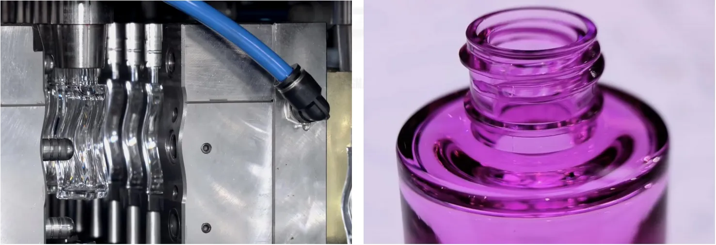
Wall thickness distribution directly determines bottle performance under real-world load conditions
The Six Root Causes of Uneven Wall Thickness
Every wall thickness defect can be traced back to one or more of the following six failure modes. Before adjusting any parameter, identify which cause — or combination of causes — is driving the deviation in your specific bottle geometry.
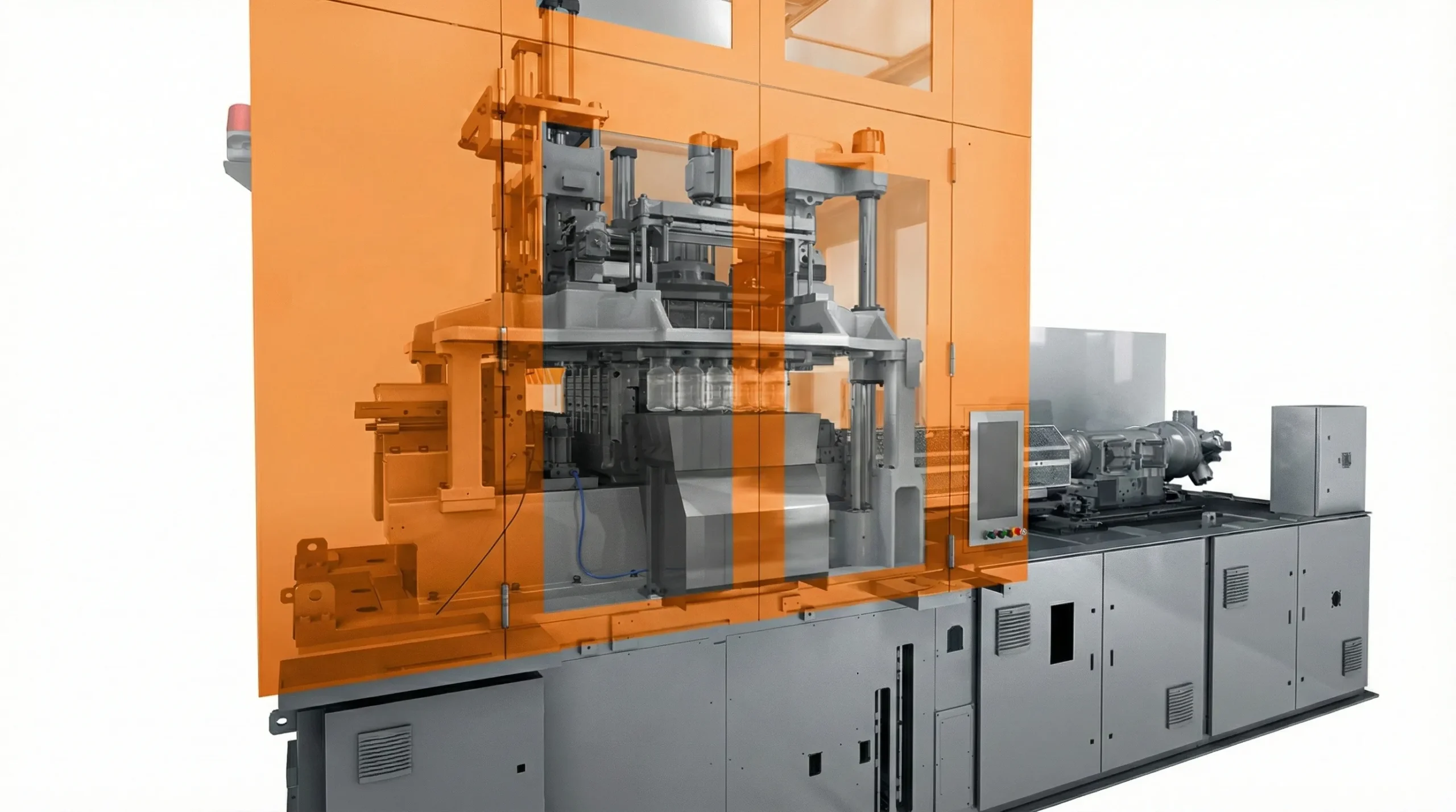
1. Non-Uniform Preform Temperature Profile
This is the single most common cause. In a einstufige Spritzstreckblasformmaschine, the preform transitions from injection directly to conditioning and blowing within the same machine cycle. If the IR heating lamps in the conditioning zone apply heat asymmetrically — due to lamp degradation, lamp positioning errors, or zone programming mistakes — certain sectors of the preform will be stiffer than others when the blow phase begins. The stiffer material resists stretching and ends up thicker; the hotter, more compliant material over-stretches and becomes dangerously thin.
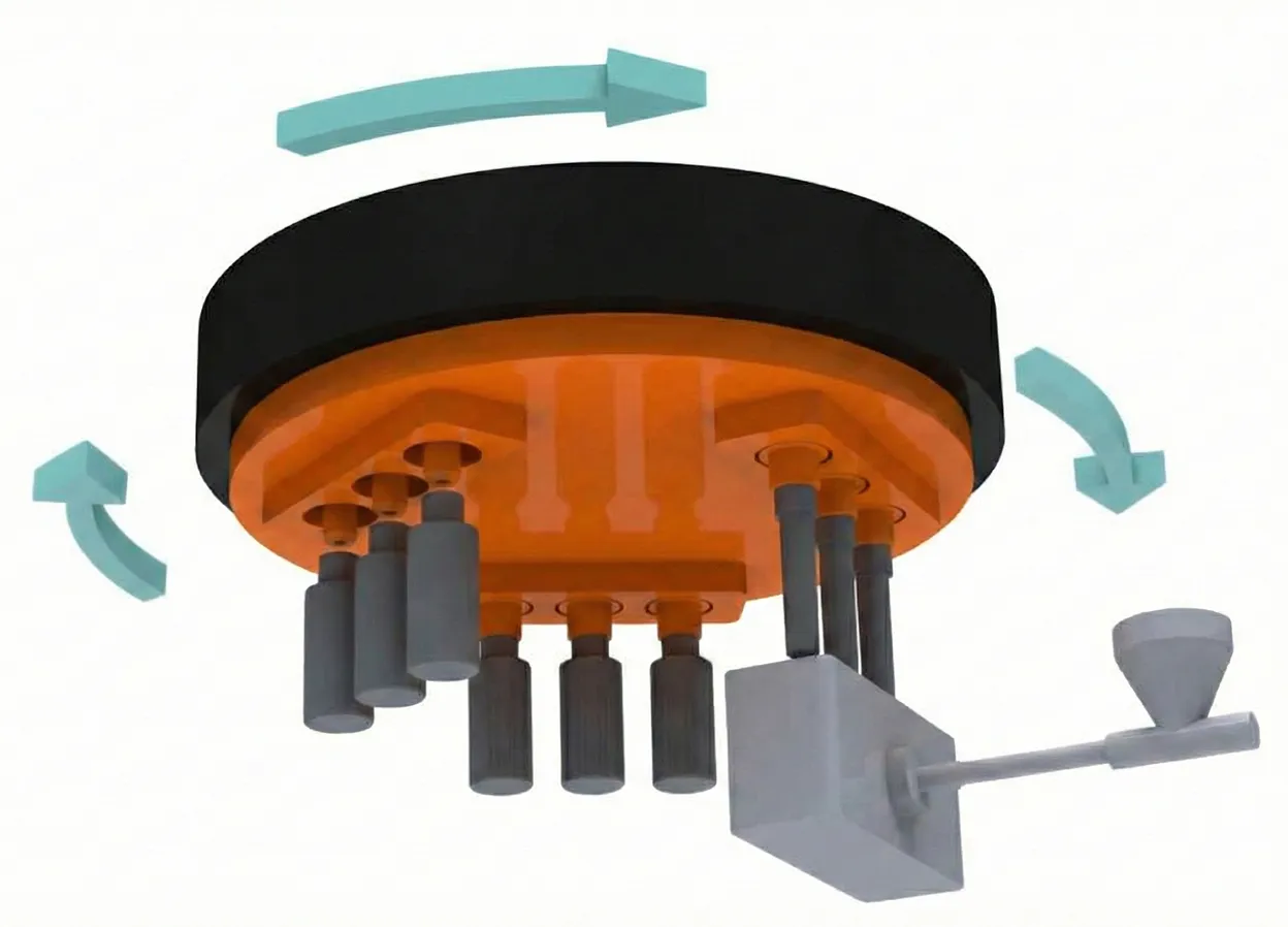
2. Stretch Rod Misalignment or Timing Deviation
The stretch rod’s sole purpose is to initiate axial orientation before radial blow pressure takes over. If the rod is not perfectly centered within the preform, it will contact one wall early and preferentially push material toward the opposite side. Similarly, if the rod descends too slowly relative to blow-air onset, the preform will begin to balloon radially before proper axial orientation is established — creating thick-bottom, thin-shoulder defects. Conversely, if the rod advances too aggressively, it can pierce or over-stretch the base dome.
3. Blow Air Pressure or Sequencing Imbalance
Two-stage blow systems use low-pressure pre-blow followed by high-pressure final blow. Incorrect pre-blow pressure, premature onset, or an excessively short pre-blow dwell time can cause uncontrolled initial expansion where material travels to the path of least resistance. This almost always means the bottom of the bottle receives insufficient material while the upper-middle body becomes too thin. Pressure spikes caused by worn solenoids or partially blocked air circuits can cause similar random variation across cavities.
4. Mold Cooling Imbalance
When cooling channels in the blow mold deliver uneven chilling — due to scale buildup, flow restriction, or poorly designed circuit routing — the material in contact with warmer mold zones remains molten longer and continues to flow slightly after the blow sequence ends. This post-blow relaxation causes local thinning adjacent to the hottest zones. Mold surface temperature delta as small as 3–5°C between cavity zones has been shown to produce measurable wall thickness variation in bottles with tight tolerances.
5. Preform Design or Gate Location Issues
A preform that is geometrically mismatched to the final bottle — too short an axial length, too thick a gate-area wall, or a gate vestige that is off-center — will always produce wall thickness problems regardless of how well the blowing process is tuned. Gate vestige protrusions act as drag points during axial stretching, creating thick annular bands directly above the gate. Likewise, preforms with excessive wall-thickness variation across their own injection-molded cross-section transfer that existing non-uniformity into the blown bottle.
6. Resin IV Variation or Moisture Content
PET resin with intrinsic viscosity (IV) below the minimum specification for the application will exhibit reduced melt strength, causing premature material migration and uncontrolled wall thinning in high-stretch-ratio zones. Similarly, improperly dried PET with residual moisture above 50 ppm will undergo hydrolytic degradation during processing — measurably lowering the working IV and producing bottles with erratic wall profiles. Even small lot-to-lot IV variation (±0.02 dl/g) can require process parameter re-optimization.
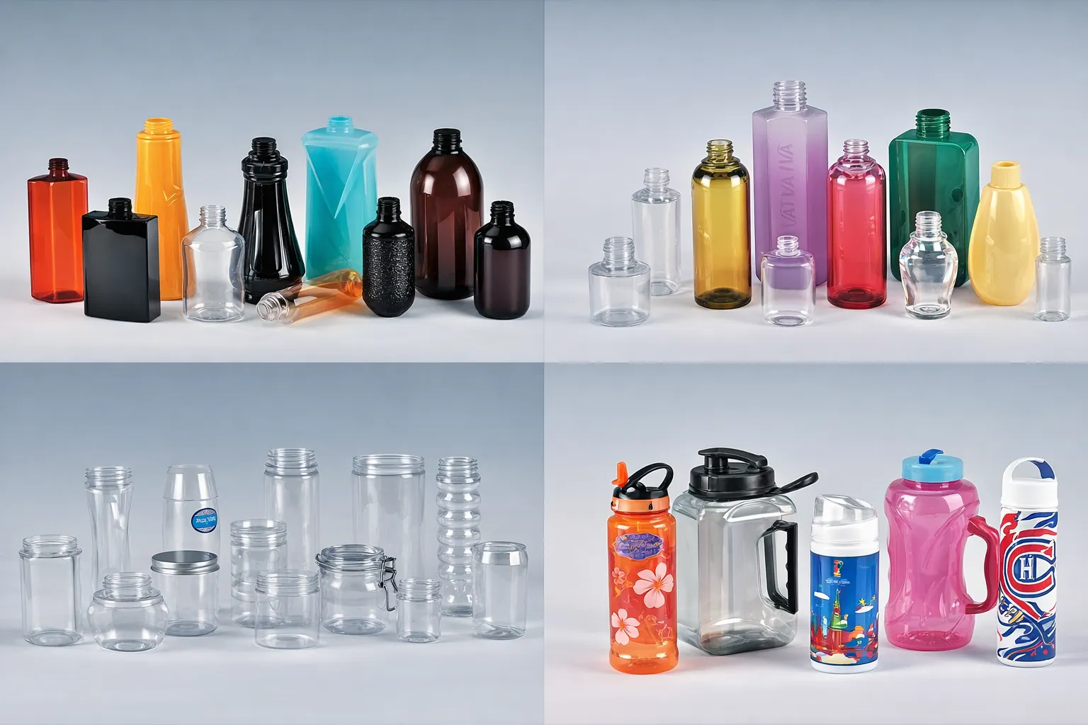
Identifying the precise defect zone on the finished bottle is the first step in root-cause diagnosis
How to Accurately Diagnose Uneven Wall Thickness
Guessing at the cause wastes time and often makes things worse. Use this four-step diagnostic sequence to generate objective data before touching any machine parameter.
Step 1 — Ultrasonic Thickness Measurement
Use a calibrated ultrasonic wall-thickness gauge (e.g., Olympus 38DL Plus or equivalent) to map the bottle at a minimum of 12 measurement points: four axial zones (base, lower body, upper body, shoulder) × three radial positions (0°, 120°, 240°). Record every reading. A well-structured measurement matrix will immediately show whether the variation is primarily axial, radial, or both — which narrows the root cause considerably.
Step 2 — Cross-Section Physical Analysis
Cut sacrificial bottles horizontally at the defect zone and measure wall thickness at each compass point using a micrometer. Examine the cut under a loupe or low-magnification microscope to identify stress whitening (indicating over-stretch), crystallinity gradients (cloudiness vs. clarity), or surface imperfections that may indicate tooling contact or venting issues. Physical cut-and-measure remains the gold standard for confirming electronic readings.
Step 3 — Preform Thermal Imaging
Use an infrared thermal camera to capture the preform’s temperature profile immediately before it enters the blow station. A well-conditioned preform should show a smooth axial gradient (cooler at the neck, warmer toward the base) with virtually no radial asymmetry. Hot or cold spots of ≥3°C compared to the nominal profile identify specific IR heating zones that require re-adjustment. This step alone resolves the majority of wall-thickness complaints in single-stage machines.
Step 4 — Multi-Cavity Correlation
On multi-cavity molds, collect and label samples from each individual cavity. If the thickness defect occurs consistently in the same cavity number across multiple production runs, the problem is tooling-specific (cavity cooling, vent location, cavity dimension) rather than a global process issue. If all cavities show the same defect pattern, it is a machine or conditioning issue. Cavity-specific vs. global defects require completely different corrective actions — mixing them up wastes significant engineering time.
Fix 1 — Optimize Preform Design and Gate Geometry
If your diagnostic data shows consistent axial wall variation — thick bottom, progressively thinner upper body — the first place to investigate is the preform itself. The preform is the “blueprint” that the blowing process attempts to redistribute; if that blueprint has inherent geometric problems, no amount of blow-process tuning will fully solve them.
Gate vestige and gate design are the most frequently overlooked preform issues. A gate vestige that protrudes more than 0.3 mm below the nominal base dome radius will act as a mechanical anchor during stretch rod advancement, preventing the base dome from being properly oriented. The result is a thick, under-oriented base with poor drop-impact resistance. Work with your preform mold supplier to reduce gate vestige height and, where possible, transition to a valve-gated hot-runner system which eliminates vestige entirely.
Preform wall-thickness profile should be designed to mirror the inverse of the stretch ratio map of the final bottle. Zones of the bottle that experience the highest bi-axial stretch ratio (typically the label panel and lower body) should receive thicker preform walls to ensure adequate material is available after stretching. This concept — called “preform distribution engineering” — is best accomplished using blow-molding simulation software (e.g., ANSYS Polyflow or Blow-SIM) before cutting any steel.
Axial wall gradient in the preform should generally be 10–20% thicker in the lower body zone compared to the upper body, for a standard 1.5L CSD bottle geometry. For wide-mouth containers, the gradient is less pronounced. For highly asymmetric bottles with significant shoulder volume, additional thickness should be concentrated in the shoulder transition zone of the preform.
Work with Hersteller von Spritzstreckblasformmaschinen who provide preform design consultation alongside machine commissioning — this integrated approach dramatically reduces the time required to reach first-article approval compared to treating preform design and machine setup as independent workstreams.
Also inspect the injection mold itself. Hot-runner imbalance in multi-cavity injection molds can produce preforms with wall eccentricity — where the inner bore of the preform is not concentric with the outer diameter. Even 0.15 mm of eccentricity translates directly into radial wall thickness variation in the blown bottle. If preform eccentricity is confirmed, the hot-runner balance and gate diameter uniformity must be corrected at the injection stage.

Fix 2 — Rebalance the IR Heating Profile
IR lamp conditioning is the process variable with the greatest leverage over wall thickness distribution — and also the one that drifts most over time as lamps age, reflectors accumulate resin vapor deposits, and lamp spacing shifts due to machine vibration. A systematic rebalancing of the heating profile is often the fastest path to resolving wall thickness complaints.
Zone-by-Zone Power Adjustment
Divide the oven into discrete axial zones corresponding to neck, upper body, lower body, and base segments. Using your thermal camera data from the diagnostic step, adjust individual lamp power in 2–3% increments. Never change more than one zone at a time, and allow 20–30 production cycles between adjustments to allow the thermal equilibrium to stabilize before re-measuring. Document every change in a structured log — this creates a referenceable baseline for future troubleshooting.
Radial Heating Asymmetry
Radial wall thickness variation — where one side of the bottle is consistently thicker than the opposite side — is almost exclusively caused by uneven radial heat distribution. This can result from a failed lamp on one side of the oven, a misaligned preform rotation mechanism that delivers inconsistent rotational speed through the heating zone, or a reflector that has sagged or shifted out of position. Check preform spin rate with a stroboscope and verify reflector geometry against the original engineering drawing.
Neck Cooling Shield Inspection
The neck finish must remain below its glass transition temperature throughout the oven passage to preserve dimensional accuracy for cap application. If the neck cooling shield is damaged, incorrectly positioned, or absent, the neck zone will absorb excess radiant energy. The resulting over-heated neck region will stretch during blow initiation, creating a “pulled neck” defect and a correspondingly thin area immediately below the support ledge. Inspect and replace neck shields at every scheduled preventive maintenance interval.
Lamp Age and Replacement Protocol
Near-infrared lamps emit maximum energy at their rated wattage only when new. After 2,000–3,000 operating hours, spectral output shifts and intensity decreases — typically by 15–25%. In a multi-lamp oven where lamps have been replaced individually as they fail rather than in planned sets, the spectral imbalance between old and new lamps alone can introduce significant thermal non-uniformity. Replace all lamps in an oven bank simultaneously, on a scheduled hours-based interval rather than waiting for visible failure.
Fix 3 — Optimize Stretch Rod and Blow Air Parameters
Once heating uniformity is confirmed, the next critical process lever is the mechanical-pneumatic stretch sequence. The interaction between stretch rod advancement speed, pre-blow onset timing, and final blow pressure ramp rate determines how material migrates from the gate region toward the base dome and body walls.
Stretch Rod Bottom Dead Center
The stretch rod must travel to within 2–4 mm of the mold base surface at its full extension (bottom dead center). Insufficient extension leaves the base dome under-oriented and thick. Excessive extension risks punching through or over-thinning the gate zone. Verify BDC position against the mold engineering drawing using a dial indicator mounted to the blow station platen — do not rely on the machine’s software display, as servo drift can introduce millimeter-level errors over time.
Stretch Rod Speed Profile
On servo-controlled systems, the stretch rod velocity profile can be programmed as multi-segment — fast initial descent to overcome preform inertia, then a deceleration phase in the final 30% of travel to allow the material ahead of the rod tip to distribute evenly into the base dome. A linear constant-speed profile is rarely optimal for bottles with complex base geometry (e.g., petaloid CSD bases). If your machine supports it, experiment with a two-speed profile before touching any pressure or temperature parameter.
Pre-Blow Pressure and Timing
Pre-blow pressure is typically set between 6–12 bar for PET, with the precise value depending on preform IV, bottle neck diameter, and target stretch ratio. If pre-blow onset occurs too early (before the stretch rod has descended past the shoulder zone), the material will balloon radially in the shoulder before axial orientation is established — creating a permanently thin shoulder and thick lower body. Delay pre-blow onset by 20–40 ms increments and observe the change in shoulder thickness. The correct onset point is where the shoulder and upper body distribute material evenly without stress whitening.
Final Blow Pressure Ramp
High-pressure final blow (typically 28–40 bar) should be applied as a controlled ramp rather than an instantaneous step change. Abrupt full-pressure application before the material has achieved close contact with the mold wall leads to “blow-through” defects where high-velocity air locally erodes and thins specific zones. A ramp time of 50–150 ms — depending on bottle volume — allows the material to gradually conform to the mold cavity while maintaining sufficient pressure to fully reproduce fine surface details and achieve proper crystallinity.
Fix 4 — Mold Tooling, Cooling, and Venting Corrections
When preform temperature and stretch-blow parameters are confirmed correct and wall thickness problems persist, the mold itself becomes the focus of investigation. Three mold-related factors most commonly drive residual wall thickness variation: cooling circuit imbalance, insufficient venting, and worn or out-of-tolerance cavity dimensions.
Cooling Circuit Audit and Cleaning
Flow-balance each cooling circuit individually using a calibrated flow meter. All circuits in a multi-cavity mold should deliver equal flow rates within ±5%. Circuits showing reduced flow are partially blocked by scale or corrosion deposits — flush them with a proprietary descaling solution under the mold supplier’s recommendations. After cleaning, re-measure mold surface temperature with a contact thermocouple under steady-state production conditions. No zone should deviate more than ±2°C from the target mold temperature.
An experienced Lieferant von Spritzgussmaschinen von ISBM will provide cooling circuit flow schematics and target delta-T specifications for each mold. If this documentation was not provided with your mold package, request it — or commission an independent CFD analysis of the cooling layout before committing to expensive physical modifications.
Mold Venting — The Often-Ignored Factor
As blow air inflates the preform against the mold cavity wall, trapped air in the cavity must escape through vent slots or vent pins machined into the mold parting line and cavity base. If vents are undersized, blocked by PET flash, or located in non-optimal positions, compressed air pockets form between the expanding preform and the mold wall. These air pockets prevent full contact and create locally thin areas adjacent to the vent-blocked zone. Vent slots should typically be 0.01–0.03 mm in depth and distributed at uniform angular intervals around the cavity perimeter at each critical geometry transition.
Cavity Wear and Dimensional Verification
Blow mold cavities are subject to progressive wear, particularly in high-speed applications running abrasive regrind-containing PET or where cooling water quality has allowed surface corrosion. Cavity diameter growth of as little as 0.1–0.2 mm results in a proportional reduction in wall thickness across the affected zone. Measure cavity internal dimensions with a 3D coordinate measuring machine (CMM) against the nominal CAD data at every 1–2 million cycles, or sooner if wall thickness trends begin to shift in SPC data.
Advanced Troubleshooting Techniques
When standard parameter adjustments fail to fully resolve wall thickness variation, or when you need to achieve extremely tight tolerances (±0.05 mm or better) for pharmaceutical or premium cosmetic applications, the following advanced techniques provide additional resolution.
High-Speed Video Analysis
Mounting a high-speed camera (1,000–4,000 fps) inside a transparent mock mold or through a purpose-drilled observation window in a production mold allows direct visual observation of the preform expansion sequence. This technique reveals the precise moment and location where material migration diverges from the target distribution — information that is simply not available from any other measurement method. It is particularly valuable for diagnosing asymmetric radial defects in bottles with non-cylindrical cross-sections.
Statistical Process Control Integration
Installing an inline ultrasonic wall-thickness measurement system (e.g., AGRINTL PETWall Profiler or similar) on the output conveyor enables 100% measurement of every bottle in production. Connecting this data stream to an SPC dashboard allows real-time detection of wall thickness drift before it exceeds specification — typically caused by lamp aging, resin lot changes, or gradual mold wear. The ability to catch and correct drift proactively, rather than reactively, is one of the defining differences between world-class and average packaging operations.
A knowledgeable ISBM-Maschinenhersteller will offer integration-ready digital I/O ports and OPC-UA communication protocols on their machines precisely to support this kind of real-time quality monitoring architecture.
Blow Molding Simulation Before Machine Trials
For new bottle programs or major bottle redesigns, investing in blow-molding simulation using finite element analysis (FEA) software allows engineers to predict wall thickness distribution in the virtual environment before cutting a single preform. Simulation can evaluate hundreds of preform geometry and process parameter combinations in hours — compressing what would otherwise require weeks of physical trials. Leading packaging consultancies and mold makers now offer simulation as a standard part of their tooling development workflow, and the ROI on projects with production volumes above 10 million units per year is typically well under six months.
Preventive Maintenance to Sustain Wall Thickness Control
The best wall-thickness results are achieved not by firefighting defects after they occur, but by maintaining machine, tooling, and material in consistently optimal condition through a disciplined preventive maintenance program. Here are the key scheduled tasks that most directly impact wall thickness performance:
Every 500 Hours
- Measure and record wall thickness baseline from 5 sample bottles per cavity
- Check IR lamp output with optical pyrometer
- Verify stretch rod alignment with dial indicator
- Inspect and clean neck cooling shields
- Check blow valve solenoid response time
Every 2,000 Hours
- Replace all IR lamps in oven bank as a complete set
- Clean and inspect oven reflectors; replace if oxidized
- Flow-balance mold cooling circuits
- Inspect stretch rod tip for wear or deformation
- Verify pre-blow and high-blow pressure transducer calibration
Annually / Per Million Cycles
- Full CMM dimensional audit of all blow mold cavities
- Cooling channel endoscopic inspection for corrosion or blockage
- Servo motor and encoder calibration verification
- Complete thermal camera survey of oven under steady-state conditions
- Incoming preform IV and dimensional audit against specification
When to Consider Equipment Replacement
Process optimization and preventive maintenance resolve the majority of wall thickness problems. However, there are situations where the fundamental limitations of an aging machine’s mechanical and control architecture make consistent wall thickness control practically impossible — regardless of how skilled the operator. Recognizing these situations early saves significant production losses and quality costs.
⚠️ Signs Your Machine May Be Limiting Wall Thickness Performance
- Stretch rod positioning repeatability exceeds ±0.5 mm cycle-to-cycle, despite servo system maintenance
- Pre-blow pressure cannot be held steady within ±0.3 bar due to worn valve components or outdated pneumatic control
- Oven zone temperature control is single-point rather than multi-zone proportional (PID)
- Machine age exceeds 15 years and no longer supports modern sensor integration for in-line quality monitoring
- Spare parts are discontinued or available only through third-party suppliers at extended lead times
For many manufacturers currently operating older platforms, the replacement of aoki injection stretch blow molding machines with modern, precision-engineered alternatives has delivered transformational improvements in wall thickness uniformity — often reducing Cpk from below 1.0 to well above 1.67 on the same bottle design. Modern machines offer servo-electric stretch rod control with encoder feedback, closed-loop blow-pressure regulation, multi-zone oven control with pyrometric feedback, and native integration with external SPC systems.
The total cost of ownership calculation for a new machine should account not only for the capital cost but also for the measurable savings from reduced material consumption (through tighter wall thickness control enabling lower preform weight targets), reduced scrap and rework rates, lower maintenance costs, and improved uptime reliability.
Häufig gestellte Fragen
Expert answers to the most common ISBM wall thickness troubleshooting questions
Q: What is the most common reason for a thick base and thin upper-body sidewall in PET bottles?
A: This pattern is the classic signature of a stretch rod that is not traveling far enough (insufficient bottom dead center extension) combined with a pre-blow onset that is occurring too early. The result is that most of the preform material stays in the lower hemisphere — thick base — while the upper body is blown thin by unconstrained radial expansion before axial stretching is complete. Verify BDC extension against mold spec and delay pre-blow onset by 20–40 ms increments until the distribution improves.
Q: Can I fix radial wall thickness variation (one side thick, one side thin) without changing the preform mold?
A: In most cases, yes. Radial variation is almost always a heating asymmetry problem caused by oven lamp imbalance, a failed lamp on one side, or inconsistent preform rotation speed through the heating zone. Start with a thermal camera survey of the preform immediately before blowing. If the temperature map confirms hot/cold asymmetry, adjust individual lamp power in the affected oven zone. If temperature is symmetric, the problem is mechanical — check stretch rod centricity and blow air inlet symmetry. A preform mold change is rarely necessary for purely radial defects.
Q: What is the acceptable wall thickness variation for standard beverage bottles?
A: For standard CSD and still-water PET bottles, most major brand owners specify a maximum wall thickness variation of ±15% from the nominal design specification at any given measurement point. For pharmaceutical containers and premium cosmetics with tight tolerances, ±8–10% is typical. Minimum absolute wall thickness for standard beverage sidewalls should not fall below 0.18–0.22 mm in the thinnest zone. The minimum base panel wall for petaloid designs is typically held to 0.25 mm or above to ensure adequate drop-impact resistance.
Q: How long does a full wall-thickness troubleshooting and optimization cycle typically take?
A: For a straightforward heating or stretch-rod timing issue, an experienced process engineer can achieve specification compliance in 4–8 hours of systematic parameter adjustment. For complex cases involving multiple interacting root causes — such as preform eccentricity combined with oven imbalance and mold cooling blockage — a full systematic resolution following the diagnostic sequence in this guide typically requires 2–4 days. Cases requiring physical mold modification (vent re-machining, cooling circuit rerouting) or preform mold revision add additional lead time but are typically resolved within 4–6 weeks including rework and production trials.
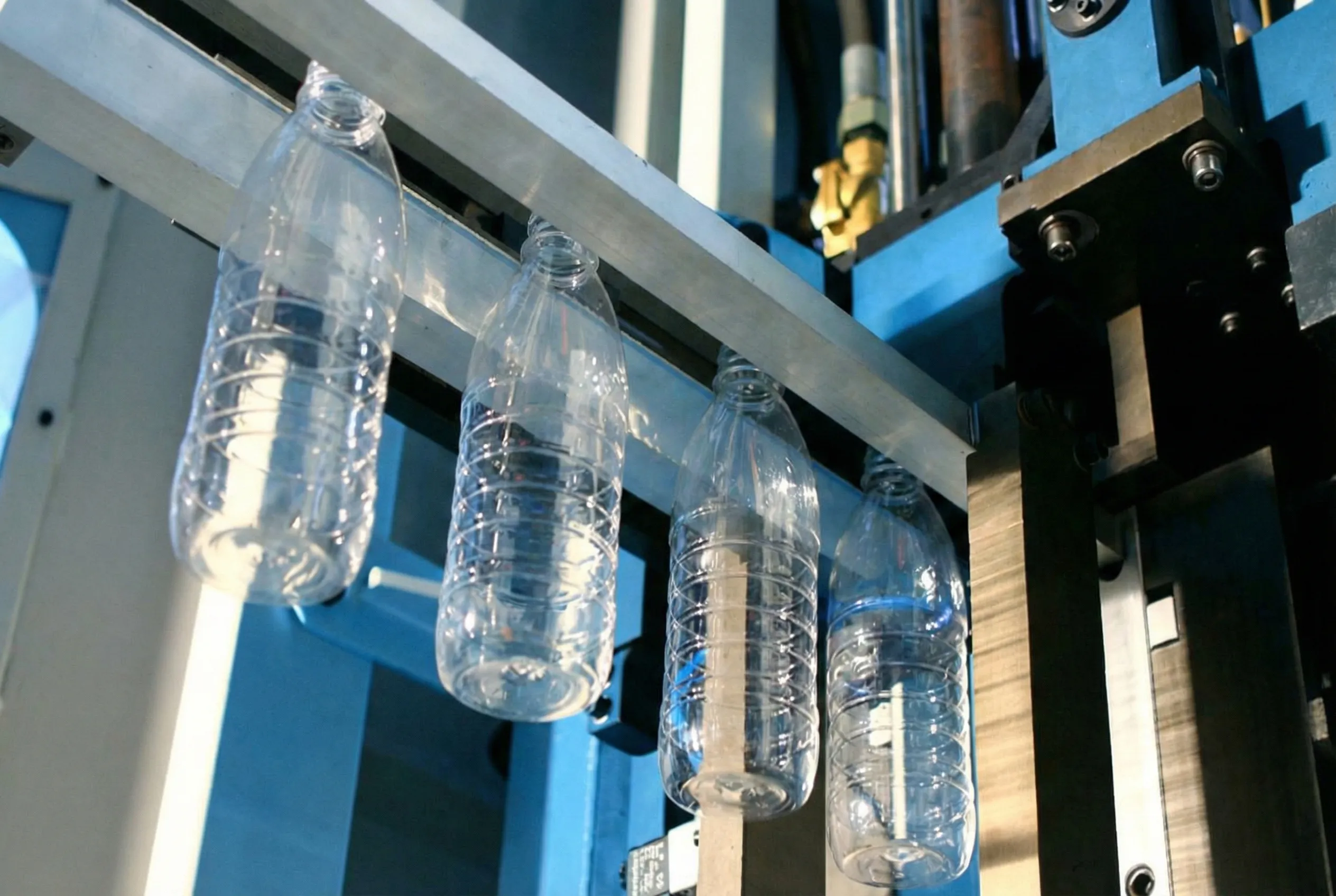
Precision ISBM Machines Built for Wall Thickness Excellence
Looking for an ISBM-Maschine zu verkaufen that delivers exceptional wall thickness control from Day 1? As a trusted ISBM-Maschinenhersteller, Ever-Power designs and manufactures single-stage injection stretch blow molding machines engineered specifically to eliminate the root causes of wall thickness variation. Our machines feature servo-electric stretch rod systems with ±0.1 mm repeatability, multi-zone closed-loop IR oven control, high-precision blow pressure regulation, and full OPC-UA connectivity for real-time quality system integration.
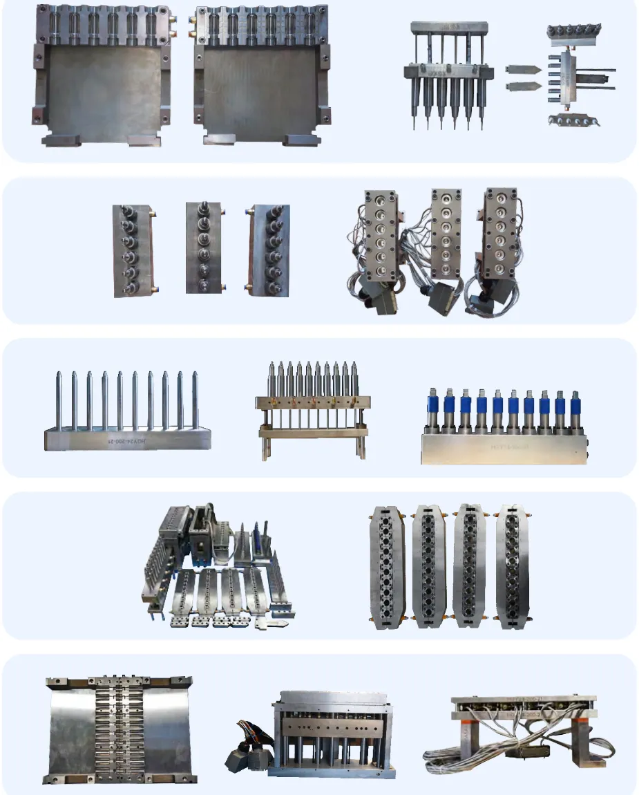
Precision ISBM Molds — Engineered for Uniform Distribution
Our mold engineering team designs and manufactures ISBM blow molds with optimized cooling circuit layouts, precisely located vent systems, and cavity geometries validated through blow simulation before steel is cut. Each mold is delivered with full cooling flow documentation and CMM dimensional certification.
Ready to Eliminate Wall Thickness Issues for Good?
Our application engineers provide free technical consultations for production lines experiencing wall thickness challenges. Whether you need process optimization support, tooling assessment, or guidance on new equipment investment as a reliable source for all your ISBM needs, Ever-Power is your partner.


